In response to the frequent occurrences of transformer short circuit accidents, we need to delve into understanding the underlying causes, examining the short circuit conditions , and strategizing to minimize their frequency and impact, checking the transformer short circuit testing . This proactive approach will be crucial in ensuring the normal operation of the power system and maintaining the reliability of the power supply.
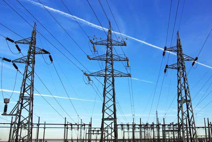
The transformer is the important part for ensuring the security and stability for power grid.With the complexity of its manufacturing and high costs, ensuring the smooth operation of the transformer holds immense significance for the power system
1. Transformer short circuit
1.1 Transformer short circuit causes
1) Structure short circuit
1.Temperature, winding method is an important factor causing transformer short circuit. Temperature has a great impact on the curvature and strength of the wire. With the rise in temperature of the wire, its curvature, strength have different degrees of decline, at the same time, the elongation of the wire will also decline.
While designing a transformer, its wiring is usually considered under room temperature conditions, often overlooking the actual operating situations. However, at the transformer’s rated capacity, the winding temperature significantly surpasses room temperature, potentially reaching upwards of 100℃
With the rise in winding temperature, its bending strength and tensile strength will be significantly reduced. Loose winding, wire and wire turns between the poor curing measures make the wire in operation easy to deformation, resulting in transformer short circuit.
2. Different types of wire on the transformer short circuit effect is not the same. Ordinary transposition wire due to its mechanical strength is poor, in the external force under the action of deformation, exposed copper occurs from time to time. In the rated current, the two parts of the torque is larger, including the transposition of the wire climbing and the winding ends of the line cake, the torque is a direct result of the conductor distortion or even deformation, which greatly increases the risk of short-circuit within the transformer.
Soft conductors were the most significant cause of transformer short circuits in the early days. Due to lack of awareness and cost issues, manufacturers use soft wires rather than hard wires in production, making the type of wire caused by the transformer short-circuit has become a more major cause.
2)Operation short circuit
Prolonged short-circuit current is the main cause of running short-circuits. Generally, when a short-circuit fault occurs within the protection range of the current interruption, the relay protection device can ensure that the fault is quickly removed without delay, taking into account the inherent delay of the mechanical action of the situation, the short-circuit current lasts for a period of time generally does not exceed 250ms, but the actual situation is different:
Firstly, due to the selective nature of the relay protection, the protection of the distribution side of the distribution side of the protection is not generally used current interruption protection, but The use of fixed-time overcurrent protection, the distribution side is also the short-circuit part;
Secondly, although the relay protection requirements of fast-acting, selective, sensitive and reliable, but it is not immune to the occurrence of relay protection device refuses to act, and when the protection refuses to act, the fault exists for a longer period of time, sometimes up to a few minutes or even a few hours, the transformer conductor to withstand the time of the large short-circuit current is increased significantly over its thermal stability will cause a short-circuit current, the transformer conductor to withstand a large period of time. Thermal stability will cause short-circuit failure;
Finally, the safe and reliable operation of the power system requires relay protection needs to be equipped with reclosing device, if the fault is a permanent fault, then the reclosing process will produce a secondary impact on the transformer, the short-circuit has just occurred when the overcurrent has been made to the transformer conductor temperature rises dramatically, the conductor’s bending has been very poor, the secondary impact current is likely to lead to transformer Short-circuit accident.
1.2 Transformer short circuit symptoms
Transformer short circuit bring great harm on the safe and stable operation of the power grid . Hence, an in-depth study of transformer short circuit symptoms will assist us in proactively scheme the preventative strategies, ultimately reduce the occurrences of transformer short circuits.
At present , the symptoms of transformer short circuit include: external short circuit, which due to the reclosing, leads to multiple impacts of short circuit . That cause severe deformation of transformer conductor coil and lead to insulation damage or even breakdown.When there is external short-circuit, frequent short-circuit shocks at short intervals will eventually lead to transformer short-circuit damage.
Transformer short-circuit damage caused by long-time short-circuit impact due to relay protection device refusal. The transformer is damaged by a short-circuit shock caused by a high short-circuit current.
2. Transformer short circuit prevention and control measures
2.1 Correct installation of transformer
Transformer in the design must meet the requirements of the actual working conditions, the installation should be in strict accordance with the rated capacity of the transformer nameplate, rated current, rated voltage, rated impedance and winding group. Installation of the transformer should have a factory certificate to ensure that the transformer is a regular manufacturer of qualified products.
The transformer’s structures should be strictly checked for quality problems, including whether its steel sections are corroded, whether the types of bolts are galvanized bolts, and whether it is equipped with flat washers and spring washers in line with its specifications. Whether the antirust paint and insulating paint have certificates of conformity.
In the construction and installation is completed, to accept its size, structure is in line with the design requirements, indoor transformer to check whether its roof leakage, whether the ground inside the house is flat and clean.
2.2 Optimal transformer protection setup
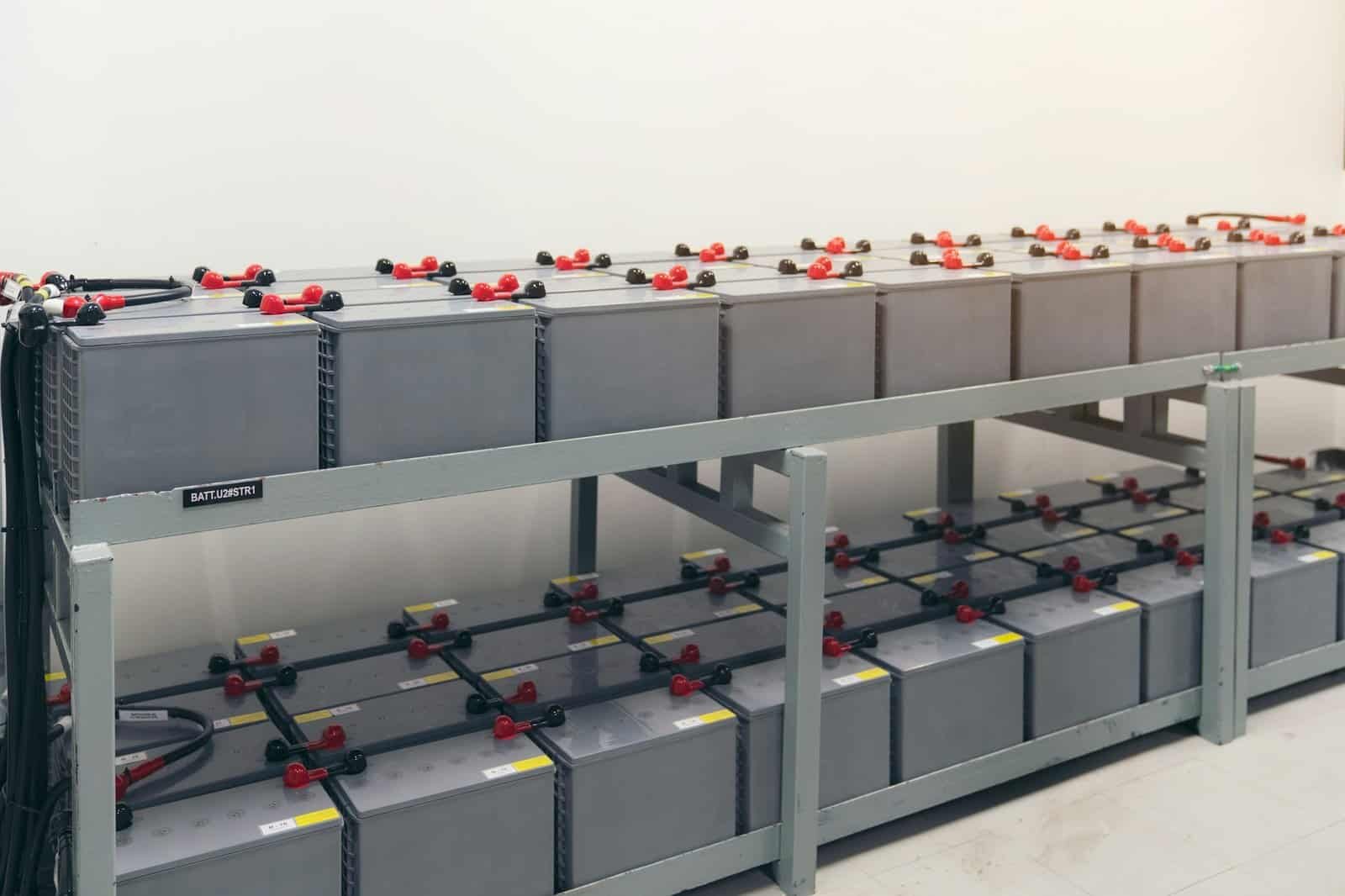
The use of microcomputer electromechanical protection makes the transformer short-circuit accident is greatly reduced, but in order to make the protection of the action of the speed, sensitivity and reliability, but also in the configuration of the protection of the installation of bus differential protection, malfunction protection, etc..
Transformer’s own protection is also important, in the transformer medium voltage side and low voltage side needs to be configured to limit the speed of the protection, so that the transformer export fault can be quickly cut off the fault, so that the short-circuit current on the transformer to reduce the impact.
In the choice of transformer, should choose a strong short-circuit resistance of the transformer, and appropriate adjustment of the main grid connection form, make the fault on the transformer impact short-circuit current is reduced. Measures to reduce the short-circuit current of the transformer is also installed on the line current-limiting reactor.
In recent years, due to insufficient switching capacity and the transformer short circuit often occurs, so in the transformer side and low voltage side of the installation of large-capacity switch is very necessary, at the same time, due to the zinc oxide lightning arrester strong ability to withstand over-voltage is also applicable to the transformer as well as the bus bar in the protection, the creepage distance is larger anti-fouling vase better insulation can effectively prevent the transformer outlet short circuit.
2.3 Analyze transformer short circuit dynamic characteristics
Grid short-circuit, short-circuit current impact on the transformer is actually the transformer winding vibration, therefore, the transformer winding vibration characteristics of the study is to prevent transformer short-circuit effective measures. The magnetic field generated by the short-circuit current will produce mechanical stress in the transformer winding, which is related to the insulation of the electromagnetic wire, winding winding, frequency, etc.. Winding intrinsic frequency and mechanical stress frequency is similar to resonance will occur, which will exacerbate the vibration of the winding.
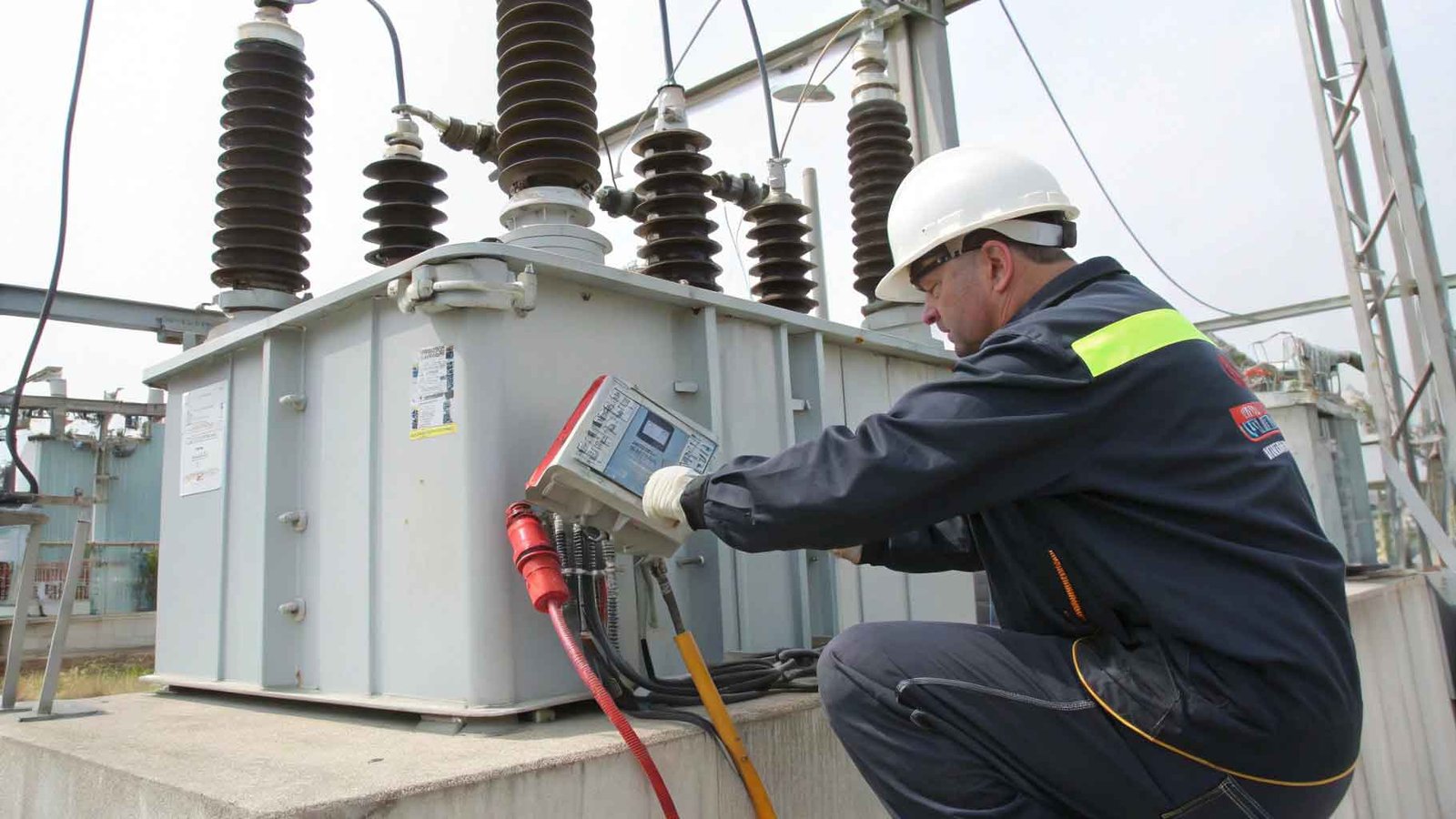
3 Transformer Short circuit impedance testing
Transformer short-circuit impedance testing is an important test in transformer engineering during the delivery, maintenance , trial and handover, which can be used to assess the short-circuit capacity of the transformer and operational safety.
3.1 The principle of transformer short circuit impedance testing
Transformer short-circuit impedance refers to the ratio of the voltage drop and the short-circuit current between the primary and secondary windings in the transformer when it is in a short-circuit state.
The magnitude of the short-circuit impedance directly affects the electromagnetic transient process and the magnitude of the short-circuit current in a short-circuit state. so it is of great significance for the short-circuit capability and operational safety of the transformer.
3.2 Transformer impedance testing method
Transformer short-circuit impedance testing is usually carried out by current injection method. Specific operational steps are as follows: first, the main winding and secondary winding of the transformer are short-circuited, and then the transformer is excited by injecting current to measure the voltage and current of the main winding and secondary winding, and finally the short-circuit impedance of the transformer is calculated according to the measurement results.
When carrying out the transformer short-circuit impedance test, the following points need to be noted. First, the test should ensure that the transformer is in normal operating condition, no load or light load operation. Secondly, the frequency of the injected current should be the same as the rated frequency of the transformer, which is usually 50 Hz.
In addition, in order to ensure the accuracy of the test, it should be checked and calibrated before the test to ensure the accuracy of the measuring instruments and equipment.
Transformer short circuit impedance value of the transformer can be obtained through the transformer short circuit impedance test, and the commonly used expression methods are percentage impedance and absolute impedance. Percentage impedance is the ratio of the short-circuit impedance of the transformer to the rated voltage, usually used to assess the short-circuit capacity of the transformer. Absolute impedance is the actual value of the short-circuit impedance of the transformer, usually used to calculate the short-circuit current of the transformer.
Transformer short-circuit impedance testing is an indispensable test in transformer engineering, which can assess the short-circuit capacity and operational safety of the transformer. Transformer impedance value can be obtained by short circuit impedance testing, which provides an important reference basis for the design, operation and maintenance of the transformer. Therefore, when carrying out transformer engineering, short-circuit impedance test must be carried out to ensure the safe and reliable operation of the transformer!