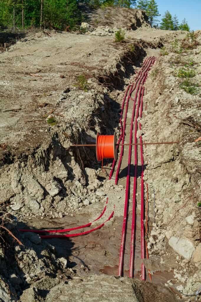
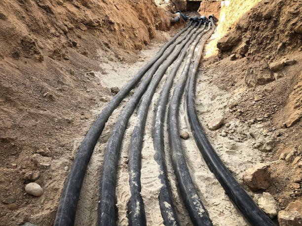
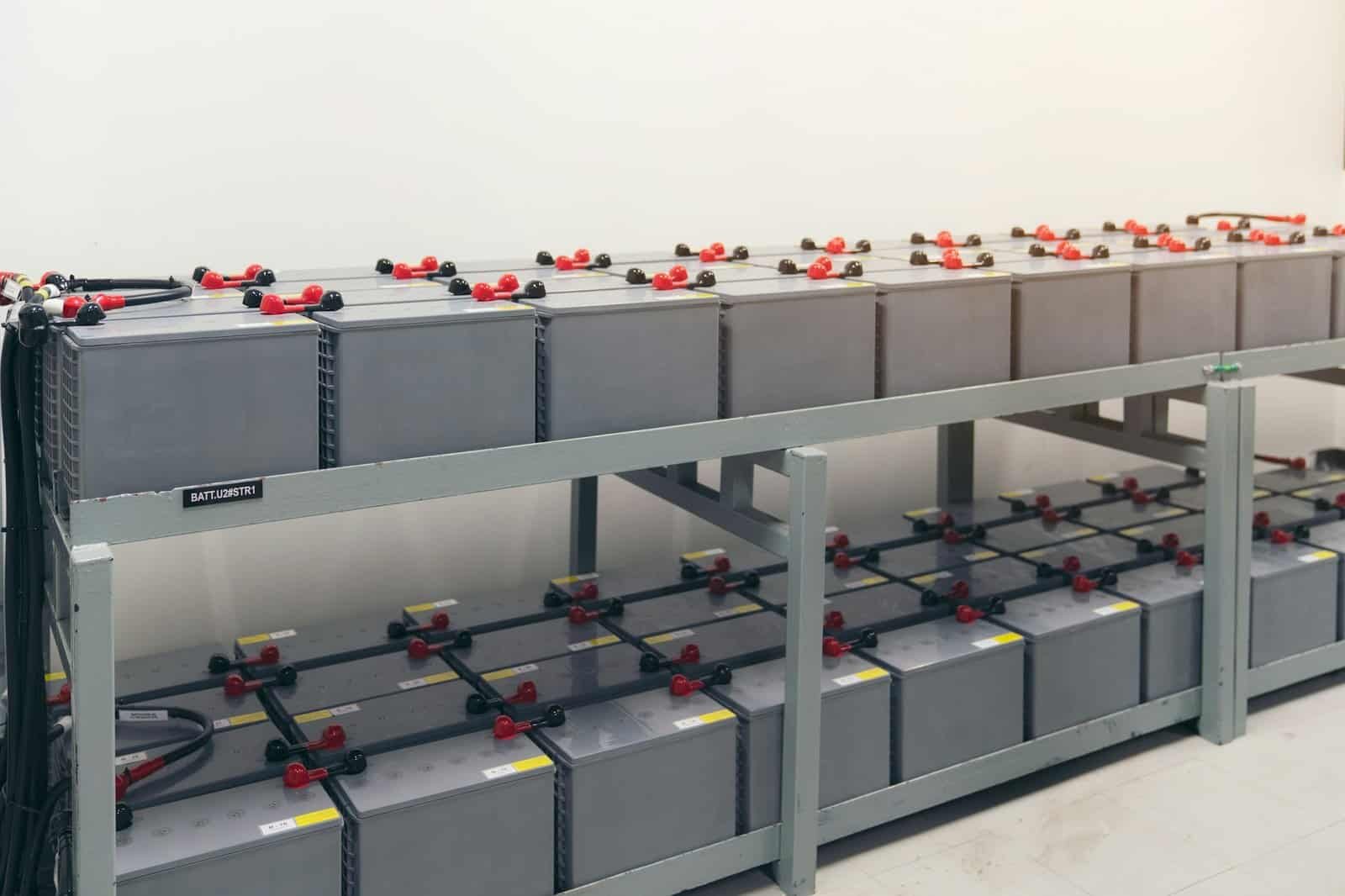
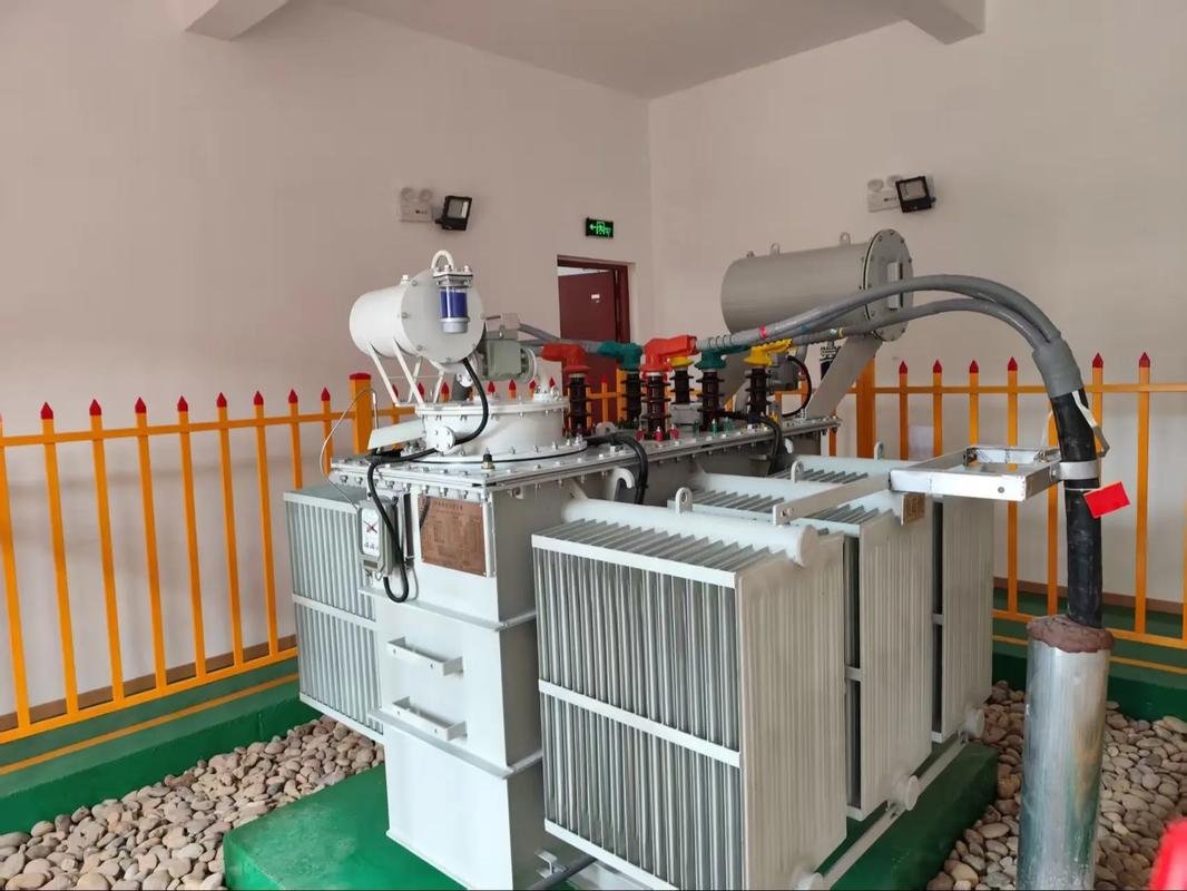
In the operation and ongoing evolution of the electric power industry, cross-linked polyethylene (XLPE) cables stand out as a critical component in power transmission. They boast superior electrical and thermal properties, robust insulation, and commendable corrosion resistance. These attributes enhance the operational efficiency of electric power equipment, fulfilling the intended function of cable usage. However, when it comes to the utilization of 35 kV XLPE cables, the issue of abnormal partial discharge poses a significant challenge. Power outages resulting from this problem accelerate cable damage, leading to economic losses for industry development and hindering sustainable industry growth. Consequently, when analyzing partial discharge issues with 35 kV XLPE cables, maintenance personnel must pinpoint the root causes and devise targeted treatment protocols to enhance cable effectiveness, aligning with the industry’s high-quality development standards.

1.XLPE cable Feature
XLPE cables are commonly found in power supply networks. Through integration with power equipment, they ensure the safety and reliability of power equipment, ultimately achieving the goals of XLPE cable monitoring management and line maintenance.The characteristics of XLPE cables are as follows:
- XLPE cable material is free from plasticizers, thus preventing the growth of mold and bacteria during actual use.
- There are no harmful components present in XLPE cables, ensuring the safety of resource transmission.
- XLPE cables exhibit superior heat resistance, maintaining a regular working temperature of around 95°C, and exceptional pressure resistance ranging between 12.5 bar and 20 bar.
- They offer improved thermal insulation, facilitating energy conservation.
- XLPE cables are constructed from stronger, more durable materials, promoting energy efficiency. They boast good strength, heat resistance, high creep strength, and a long service life, supporting the steady development of the power industry.
2. Abnormal partial discharge of 35 kV XLPE cable
The partial discharge abnormality in 35 kV XLPE cables arises from the utilization of electric power equipment and its insulation materials. By aligning breakdown field strength with applied voltage, we can quickly identify the breakdown voltage state. Following the application of pressure, the insulating material gradually deteriorates over time. This means that when partial discharge occurs within the cable insulation, it decreases the breakdown voltage, triggering the partial discharge phenomenon that necessitates analysis and resolution. In essence, partial discharge issues within cable insulation lead to a reduction in breakdown voltage, requiring targeted analysis and treatment. Typically, partial discharge abnormalities in 35 kV XLPE cables primarily manifest in the context of high-voltage electrical equipment usage
1)When air bubbles surface on the insulating materials of electrical equipment, it’s crucial that the dielectric constant of the air gap remains lower than that of the solid material. In the context of alternating currents, the strength of the electric field is inversely proportional to the dielectric constant. If the breakdown voltage of the air gap is lower than that of the solid material, it compromises the quality of processes within high-voltage electrical equipment. This discrepancy not only impacts production processes but also undermines the intended functionality of cables. Additionally, certain insulating materials may be constrained by factors affecting mechanical loads. Over prolonged usage of 35 kV XLPE cable equipment, microscopic fissures may develop in the insulating materials, creating air gaps within the cables and ultimately affecting their service life.
2)During the transportation and installation of high-voltage electrical equipment, issues may arise due to constraints in transportation schemes and installation conditions. This can lead to breakage or loosening of metal parts, preventing proper grounding of cable components and resulting in suspended potential issues within the metal parts.If the suspended potential reaches a certain threshold, the localized discharge becomes noticeable. Moreover, when insulating material becomes contaminated with electrical impurities, it can lead to cable conductor irregularities, ultimately causing a convergence of electric charges. This phenomenon results in abnormal partial discharge in 35 kV XLPE cables, disrupting their normal operation.
3)Based on the operation of high-voltage electrical equipment, different media exhibit uneven distribution on contact surfaces. Discharge phenomena occur along the cable surface, and when the conductor is surrounded by gas, localized discharge phenomena appear at the interface between the media and air. This phenomenon affects the cable’s effectiveness and prevents achieving the goal of partial discharge analysis and treatment in 35 kV XLPE cables. Due to partial discharge, insulation materials of high-voltage electrical equipment suffer damage. Charged particles in the insulation medium cause localized temperature increases, ultimately leading to softening of the insulation medium and a continuous decrease in electrical performance. Moreover, when partial discharge occurs in 35 kV XLPE cables, issues such as chemical decomposition, carbonization, and intense oxidation occur under high temperatures, increasing safety risks for electrical equipment and failing to meet the requirements for normal use of power equipment.
3.Partial discharge of 35 kV XLPE cable Methods
3.1 DC Voltage Stacking Technique
The use of DC voltage stacking technology gradually leads to insulation deterioration during operation. As DC voltage is applied to the cable, corresponding DC current emerges based on the degree of degradation. This current, indicative of the degradation level, is then applied to the cable, and the cable’s insulation is calculated through an online method using parameters of the superimposed DC voltage and the measured current. Subsequently, the insulation resistance of the cable is determined using the same online method, facilitating accurate assessment of the insulation degradation state.
Overall, the technical characteristics of the DC superposition method are as follows:
1)Corresponding values can be measured via insulation resistance and conventional methods within the DC voltage superposition technique.
2)Actual measurement can be conducted using the DC voltage superposition method. However, due to substantial variations in stray current within the ground during measurement, there is a relatively high margin of error.
3)When DC current remains energized for an extended period, passing directly through the voltage transformer TV,it will cause the magnetic circuit of the transformer to be saturated.
When the current passes directly through the voltage transformer TV, it will cause the magnetic circuit of the transformer to be saturated, which will cause the relay to operate incorrectly.
The study and analysis of this operation process can realize the purpose of DC voltage superposition analysis and ensure that the cable and power system can be analyzed.
3.2 Dielectric loss technology
For addressing the abnormal partial discharge situation in 35kV cross-linked polyethylene cables, loss current measurement is essential to achieve loss analysis, necessitating an in-depth analysis of the cross-linked polyethylene cable’s losses. During measurement, to ensure accurate loss analysis, the power cable must undergo thorough examination. The current induced by AC voltage must be meticulously analyzed, followed by a comprehensive analysis of the capacitive current component, loss current component, and water tree deterioration cable insulation resistance value to prevent increased loss current. However, separating the capacitive current component from the loss current component poses a relative challenge due to the relationship between loss current and capacitance, as well as tanδ. Determining the relationship between capacitance and tanδ and establishing limit parameters based on the average value of the voltage application period is crucial. The loss current measurement technique is typically employed in 35 kV XLPE cables.
The general measurement procedure for this technique involves considering water trees as collections of voids. When subjected to a high electric field, the water within these voids stretches in the direction of the electric field under Maxwell stress, leading to an increase in current. To avoid waveform distortion in the case of DC leakage currents in water trees, comprehensive analysis of current and voltage characteristics is required. The loss current measurement technique not only accurately detects water tree deterioration but also measures the loss current of water through trees。
The dielectric loss measurement technology not only accurately detects the deterioration of water passing through trees but also diagnoses and analyzes non-through-tree water, thereby fully demonstrating the benefits of online monitoring. This fully embodies the advantages of online monitoring and achieves the objective of loss current analysis and processing
3.3 Partial Discharge Technology
Through the utilization of partial discharge technology and the implementation of online monitoring technology programs, it is possible to establish a comprehensive insulation power equipment management program. Specifically tailored to 35kV XLPE cables, it is imperative to analyze partial discharges stemming from branching through the cable.
By implementing localized online monitoring methods, such as electromagnetic wave, ultrasonic, and pulse phase analysis techniques, precise determination of cable measurement points can be achieved. Subsequently, through comprehensive analysis of measurement joints and cable discharge conditions, the signal state is scrutinized to enhance the overall effectiveness of partial discharge detection.


