Transformer insulation failure causes big problems. Unexpected downtime costs money and reputation. Dielectric testing helps prevent this, ensuring your equipment stays reliable and operational when you need it most.
Dielectric tests check a transformer’s insulation strength. They apply specific voltages to ensure the insulation can handle electrical stress without breaking down. This confirms the transformer’s integrity and reliability for safe operation.
Understanding these tests is important for anyone involved with transformers. We see it all the time – poor insulation is a major cause of failure, leading to costly repairs and significant outages for companies like the ones Muhammad in Saudi Arabia supports, or the transformer manufacturers like Spencer’s company. Let’s look at the key dielectric tests you need to know about. These tests verify different aspects of the transformer’s insulation system, ensuring they meet the required standards and operate safely. Knowing these tests helps you choose the right equipment and maintain your power systems effectively.
What is the Separate Source Voltage Withstand Test of a Transformer?
Worried about insulation between windings and ground? A failure here is serious and can lead to major damage. The Separate Source Voltage Withstand test directly checks this critical insulation before problems occur.
This test, often called the Withstand Voltage test, uses a high AC voltage from an external source. It’s connected between one winding and all other windings/grounded parts. This verifies the main insulation integrity against phase-to-ground stresses.
This test is fundamental for verifying the primary insulation of a transformer. It ensures the insulation between the windings themselves, and between the windings and the grounded core or tank, is strong enough.
Test Procedure Explained
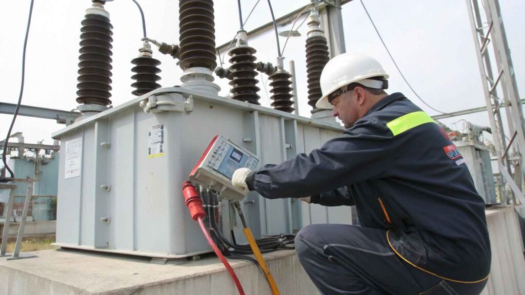
We connect a high voltage AC source to the terminals of one winding. All terminals of other windings, along with the transformer tank and core, are connected to ground. The voltage is gradually increased to the specified test level, held for a standard duration (typically 60 seconds according to standards like IEC 60076-3 or IEEE C57.12.90), and then gradually decreased. The test is successful if no breakdown (sudden drop in voltage, increase in current) occurs.
What it Verifies
The primary purpose is to check the phase-to-ground and phase-to-phase insulation strength. It stresses the major insulation components like:
- Insulation between high voltage (HV) winding and low voltage (LV) winding.
- Insulation between HV winding and the grounded tank/core.
- Insulation between LV winding and the grounded tank/core.
- Bushing insulation strength.
Key Considerations
- Test Voltage: The voltage level depends on the transformer’s rated voltage and insulation level (BIL – Basic Insulation Level). Standards define these levels precisely.
- Safety: This involves high voltages, so strict safety protocols are essential. Proper grounding and clearance are critical.
- Equipment: A reliable high-voltage AC test set (like those we manufacture at KV Hipot) capable of delivering the required voltage and current is necessary. Accurate measurement is key.
This test is usually performed on each winding sequentially. It’s a routine test performed on every transformer unit produced.
How Does the Applied Voltage Test Work on a Transformer?
Need to confirm your transformer meets insulation standards before putting it into service? Doubts can lead to rejected projects or unexpected failures. The Applied Voltage test provides that crucial proof of insulation integrity.
The Applied Voltage test directly stresses the major insulation system. It applies a high voltage, usually power frequency AC, between windings and grounded parts for a specific time, typically 60 seconds, proving its withstand capability against overvoltages.
This test essentially confirms that the main insulation structure of the transformer, the barriers between windings and between windings and ground, can handle voltage stresses significantly higher than its normal operating voltage. It’s a go/no-go test critical for quality assurance.
Purpose of the Test
The core goal is verification. Does the transformer’s insulation meet the design specifications and industry standards? It simulates potential overvoltage conditions (though not lightning impulses, which require impulse testing). Passing this test gives confidence in the transformer’s ability to withstand temporary overvoltages encountered during operation. It’s a standard requirement in both type tests (design validation) and routine tests (production quality check).
Test Parameters
- Voltage Source: An external AC high-voltage source, separate from the transformer’s own windings.
- Frequency: Typically performed at the power system frequency (50 Hz or 60 Hz).
- Duration: Usually 60 seconds after reaching the full test voltage.
- Voltage Level: Defined by standards based on the transformer’s voltage class and insulation level.
Connection Example
To test the High Voltage (HV) winding insulation:
- Connect all HV terminals together.
- Connect all Low Voltage (LV) terminals together and connect them to ground.
- Connect the transformer tank and core to ground.
- Apply the specified test voltage between the connected HV terminals and ground using the external HV test set.
- Monitor for any signs of insulation breakdown (e.g., flashover, puncture, significant current increase).
Reliable test equipment is paramount for accurate results. At KV Hipot, we provide robust AC Hipot testers designed for these demanding applications, ensuring our clients can perform these vital tests with confidence.
What is the Induced Voltage Test (IVT) of a Transformer?
Concerned about insulation between turns or layers within a winding? Standard tests don’t fully stress this. An Induced Voltage Test specifically targets this turn-to-turn insulation, preventing internal winding faults.
The Induced Voltage Test applies a higher-than-normal voltage across a transformer winding, but at a higher frequency. This induces the necessary voltage stress between turns and layers without saturating the core, verifying inter-turn insulation.
This test is crucial because the Separate Source test primarily checks the main insulation to ground and between windings, not the insulation within a single winding. Turn-to-turn failures can be subtle initially but lead to catastrophic failure later. We often explain to clients like Spencer, who manufactures transformers, that this test is essential for their factory acceptance procedures. It catches manufacturing defects that other tests might miss. It directly addresses the need for high product quality and reliability, key points for buyers sourcing equipment.
How it Differs
Unlike the Applied Voltage test using an external source, the IVT uses the transformer itself. We apply voltage to one winding (usually the Low Voltage winding because it’s easier to manage the input voltage) to induce a proportionally higher voltage in the other winding(s). To avoid core saturation at these higher voltages, we must increase the frequency of the applied voltage (typically 100 Hz to 400 Hz, depending on the standard and transformer design). The test voltage is usually twice the rated voltage of the winding under test.
Test Execution
- The transformer windings are connected appropriately. Usually, the HV winding is left open-circuit or lightly loaded, and voltage is applied to the LV winding.
- A variable frequency generator supplies power.
- The voltage is raised to the target level, inducing typically 2x rated voltage in the HV winding.
- The test duration depends on the frequency (e.g., 60 seconds at nominal frequency, adjusted inversely proportional to frequency, but with minimum durations specified by standards like IEC 60076-3).
- During the test, we listen for abnormal noise and monitor currents for signs of breakdown. Sometimes, Partial Discharge (PD) measurements are performed simultaneously (Induced Voltage Test with PD measurement – IVPD).
What it Detects
- Weak insulation between adjacent turns.
- Faults in layer insulation.
- Problems with tap changer connections or winding leads within the winding structure. Passing the IVT gives confidence that the internal winding structure is sound.
Why is Partial Discharge (PD) Measurement Important During Dielectric Tests?
Are your dielectric tests just pass/fail? What if there are hidden defects slowly degrading the insulation? Partial Discharge measurement detects these hidden issues before they cause a complete breakdown.
Partial Discharge (PD) measurement detects small electrical sparks or discharges occurring within the insulation system. Performing PD tests during induced or applied voltage tests identifies weaknesses that might pass a simple withstand test but cause long-term failure.
Think of PD as tiny sparks eating away at the insulation. A simple voltage withstand test might not show immediate failure, but these discharges indicate a problem is developing. This is critical information for ensuring long-term reliability – a major concern for clients like Muhammad, who need equipment to perform reliably for years on project sites. Detecting PD early allows for corrective action before a catastrophic failure occurs in the field, preventing costly downtime and potential safety hazards. At KV Hipot, our PD testing equipment helps provide this deeper insight.
Understanding Partial Discharges
PD occurs in localized areas within the insulation system where the electric field strength exceeds the breakdown strength of that small portion, but not enough to bridge the entire insulation path. Common locations include:
- Voids or cavities within solid insulation (e.g., paper, pressboard).
- Bubbles within liquid insulation (transformer oil).
- Interfaces between different insulating materials.
- Sharp points on conductors causing high local stress.
PD Measurement During IVT/Applied Voltage
Standards increasingly require or recommend PD measurement during induced voltage tests (IVPD) and sometimes applied voltage tests.
- Setup: Sensitive PD detection equipment (like our KV Hipot PD detectors) is connected to the transformer terminals, usually via coupling capacitors and measuring impedances.
- Calibration: The system is calibrated using a known charge injection pulse.
- Measurement: As the voltage is raised during the dielectric test (e.g., IVT), the PD levels are continuously monitored. The voltage is typically raised to a pre-stress level, then lowered to the specified test voltage where PD is measured against acceptance criteria (usually a maximum permissible level in picoCoulombs, pC).
- Analysis: The magnitude and pattern of PD pulses can sometimes help identify the type and location of the defect.
Benefits of PD Testing
- Early Defect Detection: Finds problems missed by simple withstand tests.
- Quality Assurance: Provides a more sensitive measure of manufacturing quality.
- Condition Assessment: Can be used for diagnostics on transformers already in service.
- Improved Reliability: Helps prevent unexpected in-service failures by identifying developing faults. Incorporating PD measurement offers a much higher level of confidence in the transformer’s insulation integrity.
Conclusion
Dielectric tests are vital for transformer reliability. Tests like Separate Source, Induced Voltage, and Partial Discharge measurement verify insulation strength, ensuring safe operation and preventing costly failures.