The substation battery serve as the final line of defense for the DC system, reliably supplying power to the critical primary and secondary equipment in the station, even during an AC fault state. This ensures the correct function of safety devices and guarantees the safe operation of the power grid. Currently, most substations utilize valve-regulated lead-acid batteries, which experience a decline in capacity and an increase in internal resistance after 4 to 5 years of use, ultimately resulting in the faults.
The high voltage used in substations is created by dozens, or even hundreds of battery units connected in series. This means that any abnormality in a single unit can result in a significant drop in the overall battery pack’s performance, or worse, lead to a serious substation accident.
If a indvidual battery becomes open-circuited. Due to the sealed environment of valve-regulated lead-acid batteries, their internal condition cannot be regularly inspected, leading to a greater risk of hidden open-circuit faults.
This article analyzes the main causes of open circuits in substation batteries and proposes preventative measures, including methods for detecting and preventing battery open-circuit faults
1. Battery open-circuit causes and detection methods
A normal 2V 300AH battery has an internal resistance of around 0.5mΩ. During discharge, a small reverse voltage is generated due to the internal resistance, with higher internal resistance resulting in a greater reverse voltage. The voltage drop at positive end gradually increases, and when the cell internal resistance increases to a certain value, the voltage at the positive end is almost 0. If the internal resistance increases further, it can affect the battery pack’s ability to discharge properly, leading to irreparable damage.
In the case of an open circuit failure in a valve-regulated lead-acid battery, there may be positive plate grid corrosion, water loss, thermal runaway, negative plate sink corrosion, sulfation, and other failures that increase the battery’s internal resistance
(1) Water loss and thermal runaway of batteries
Water loss is a specific fault of valve-regulated lead-acid batteries. High float charging voltage and current can reduce the efficiency of oxygen recombination reaction, leading to an increase in internal pressure and gas discharge, which can result in water loss.
The lack of water in the battery can reduce the activity of ions involved in the electrochemical reaction, causing an increase in internal resistance. The battery pack may undergo cumulative enhancement under the multiple effects of charging current, temperature, and water loss, ultimately leading to thermal runaway and irreversible damage to the battery.
(2) Sulfation of negative electrode plate
Long-term undercharging or semi-discharged storage can cause the active material lead sulfate on the negative plate to recrystallize and form hard and coarse lead sulfate. If the lead sulfate cannot chemically react inside the battery within a short period, it will lose its activity and will not be able to participate in the chemical reaction later.
(3) Corrosion of positive plate grid
In the float charging process, the potential of the whole plate grid is higher than that in the flowing electrolyte battery due to the recombination of oxygen. The positive plate grid is in a higher acidic environment, making it easy to corrode, which is one of the important factors limiting battery life. Water loss or high ambient temperature during battery operation can increase the specific gravity of the electrolyte, accelerating the corrosion of the positive electrode plate and reducing the active material of the plate, eventually leading to low battery capacity.
(4) Negative sink fracture
When the cathode plate grid corrodes, it increases the oxygen precipitation reaction on the cathode, intensifying the oxygen compound reaction and corrosion rate of the cathode sink. Additionally, electrolyte water loss increases the oxygen transfer channel, further intensifying the oxygen compound reaction and increasing the risk of thermal runaway.
In summary, these causes of battery failure are mutually reinforcing and result in increased internal resistance and decreased capacity. For batteries with gradually increasing internal resistance, daily voltage, internal resistance, and nuclear capacity detection methods can be used for detection. Current battery configurations in substations have sufficient redundancy, even if the capacity drops to 80%, it can still support the load power.
Under normal voltage, internal resistance, and 0.1C nuclear capacity discharge conditions, the electrical performance value of the battery remains normal. However, if there is an AC power loss, substations require higher current power supply in the early stage, and severely corroded bus bars may burn off, causing the battery pack to be open-circuited and lose its proper function.
During battery discharge, the internal resistance of the battery causes voltage dips, including the resistance of the diaphragm filled with electrolyte, the ohmic resistance of the plate grid, the resistance of the active substance, and the solid-solid, solid-liquid contact surface and electrolyte resistance. The change in the battery’s internal resistance can be characterized by the characteristic curve of voltage dip. The higher the discharge current, the larger the voltage deviation value, and the characteristic curve will be more obvious, as shown in Figure 1.
After an instantaneous high current discharge of 6ms, a battery with 100% nominal capacity experiences a small voltage drop, while a battery with 80% nominal capacity experiences a minimum voltage drop to 1.9V, and a battery with 10% nominal capacity experiences a voltage drop to 1.8V
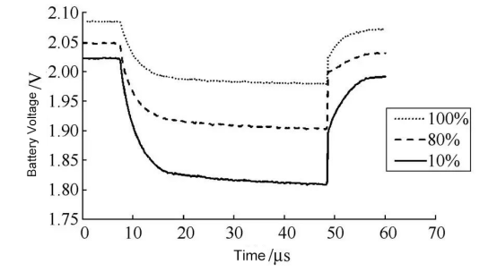
Figure 1
The high current short time discharge method is used to detect the melt disconnection of the plate grid and sink. When there is a welding problem or corrosion between the plate grid and sink, other plates need to bear more current and the melt accelerates, causing a vicious circle, which eventually leads to complete disconnection of the plate and sink.
However, it is important to consider the problem of high current discharge damage to the battery when the discharge current exceeds a certain range. It is usually recommended to select a discharge current within 0.3~0.5C to obtain a more accurate internal resistance test and avoid damage to the battery.
2. Prevention measurement for Battery open cuircuit
To prevent open circuit batteries, it is important to recognize that open circuit issues develop over a long period of time, and some open circuit batteries may not be detected in a timely manner with existing detection mechanisms. With the trend towards unattended substations, preventing battery open circuit issues is becoming increasingly important.
(1) Regularly discharge the battery with high current for a short period of time and record the voltage of each battery unit online. The discharge data can calculate the internal resistance of the battery and judge the performance of the battery. By checking the load capacity characteristics of the battery, hidden open-circuit batteries can be screened. It is recommended that the online discharge current is not less than the maximum value of the local load current.
(2) Abandon the traditional concept of “sealed” and “maintenance-free” of valve-regulated lead-acid batteries. When the trend of capacity decline occurs during the operation of the battery, consider using the means of charging and discharging activation repair by adding repair solution to restore the capacity of the battery. This can help restore the battery internal resistance to the factory level and alleviate the speed of battery internal corrosion of positive plate grid, electrolyte drying, negative sink corrosion, etc.
(3) Strictly implement regular verification annual capacity test of the battery pack, and monitor the voltage data of the battery pack and each battery unit during charging and discharging. Store the data in the file through the database. Further testing of abnormal batteries in the battery pack is screened by horizontally comparing the curves of the voltage of each battery unit in the whole battery pack. Additionally, vertically comparing the voltage change trend on the time axis of individual batteries can make a prediction on the trend of battery performance change.
3. How to check the battery capacity in substiton ?
One of the major concerns for substation operation and maintenance engineers is checking the battery capacity and monitoring the voltage data of each individual battery unit during discharging. To solve these issues, KV Hipot Power Equipment Company has developed a series of professional battery testing and maintenance equipment, including battery discharger, which is used for checking battery capacity and testing equipment.