
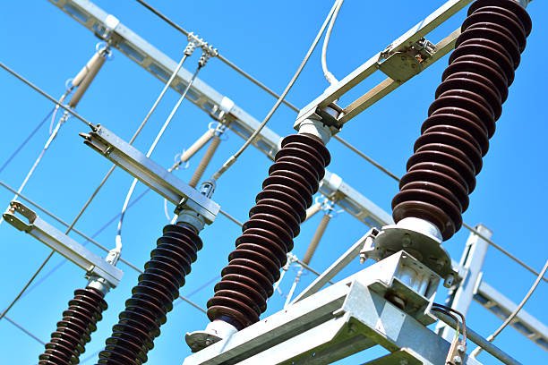
In modern society, as a key driving force for economic development and social operation, the stable supply of electric power is crucial. High-voltage switches are the core equipment in the power system, widely used in power plants, substations, industrial enterprises and urban power grids and other links. High-voltage switches can realize the rapid connection and disconnection of circuits under the environment of high voltage and high current to ensure the normal operation of the power system and fault isolation.
Once the high-voltage switch and high-voltage switchgear failures, it is very likely to cause large-scale power outages, bringing great losses to social production and people’s lives. In some large-scale industrial production, a sudden power failure may lead to the interruption of the production line, resulting in a large amount of raw material waste and product scrapping; in the urban power grid, a power failure will affect the normal life of the residents, triggering a series of problems, such as traffic congestion, communication disruption and so on.
Through the acceptance test for electrical testing of High voltage circuit breaker, the performance indexes of the equipment can be comprehensively tested, potential defects and hidden dangers can be found in time to ensure that the equipment can work stably and reliably for a long time after it is put into operation. This not only helps to improve the power supply quality of the power system and reduce the incidence of blackout accidents, but also provides a strong guarantee for the safe production and economic benefits of power enterprises.
1.The working principle and common types of high-voltage switches
1.1 Working Principle of Different Types of High Voltage Switches
Oil circuit breaker is a kind of high-voltage switch widely used in the early days, and its working principle is based on the gas generated by the decomposition of insulating oil under the action of high temperature of electric arc to extinguish the arc. In the breaking process, the movable and static contacts separate to produce an arc, the arc makes the surrounding insulating oil decompose rapidly, forming a large number of hydrogen, acetylene and other gases, these gases in the arc extinguishing chamber to form a high pressure to promote the oil flow blowing to the arc, so that the arc is rapidly cooled, elongated and ultimately extinguished. Multi-oil circuit breaker insulating oil is not only used to extinguish the arc, but also as an insulating medium between the charged part and the grounding shell, its structure is relatively simple, but the volume is huge, the amount of oil, there is a risk of fire and explosion. Less oil circuit breaker is to reduce the amount of insulating oil, only the insulating oil as an arc extinguishing medium, the charged part of the shell and the grounding of the insulation between the insulator and other materials, compared with more oil circuit breaker, its volume is smaller, safety has improved, but still need to regularly test and maintain the insulating oil.
Vacuum circuit breakers use a high vacuum environment to quench the arc. The arc extinguishing chamber is made of ceramic or glass and other insulating materials, the interior is pumped into a high vacuum, dynamic and static contacts are sealed in the arc extinguishing chamber. When the circuit breaker breaks, the contact separation generated by the arc in the vacuum quickly spread, because there is almost no gas molecules in the vacuum, the arc can not be maintained, and thus quickly extinguished. Vacuum circuit breaker has the advantages of small size, light weight, fast action, short arc burning time, long service life, no danger of explosion, etc. It is suitable for frequent operation occasions, such as power distribution rooms of industrial enterprises and opening and closing houses of urban distribution networks.
SF6 circuit breakers use SF6 gas as insulation medium and arc extinguishing medium, SF6 gas has excellent insulation and arc extinguishing ability, and its insulation strength is about 2.5 – 3 times that of air. When the circuit breaker is open, the high pressure of SF6 gas will blow out the arc. SF6 circuit breaker usually adopts pressure gas, self-energy or hybrid arc extinguishing method. Pressurized SF6 circuit breaker through the piston compression SF6 gas, the formation of high-speed gas flow blowing to the arc; self-energized SF6 circuit breaker is the use of the arc’s own energy heating and compression of SF6 gas, resulting in blowing the arc gas flow; hybrid SF6 circuit breaker combines the advantages of the pressurized and self-energized SF6 circuit breaker has a strong breaking capacity, high voltage at the breakpoint, easy to maintain and easy to operate, and long service intervals and so on, and is widely used in high-voltage and ultra-high-voltage circuit breaker. It is widely used in high-voltage and ultra-high-voltage power systems.
2. Test standards for high-voltage switches
A series of standards formulated by the International Electrotechnical Commission (IEC), such as the IEC 62271 series standards, provide detailed regulations on the test methods and technical requirements for high-voltage switchgear and control equipment, which provide an important reference for the acceptance tests of high-voltage switches and high-voltage switchgear on a global scale. The Institute of Electrical and Electronics Engineers (IEEE) has also issued numerous related standards, such as the IEEE Std C37 series of standards, which have a wide influence in the performance testing and reliability assessment of high-voltage switchgear. Under the guidance of these standards, foreign electric power enterprises and equipment manufacturers focus on comprehensive and strict testing of various performance indexes of the equipment in the acceptance test process to ensure the high quality and reliability of the equipment.Internationally renowned electrical equipment manufacturers, such as ABB and Siemens, use advanced automated test equipment and high-precision testing instruments in the R&D and production process of high-voltage switchgear, and are able to assess the mechanical characteristics, electrical performance, reliability and reliability of the equipment. equipment’s mechanical characteristics, electrical performance, insulation performance, etc. are accurately measured and analyzed, so that potential faults can be found in advance and the reliability and safety of the equipment can be improved.
3. High-voltage switch acceptance test
3.1 Acceptance test item contents
3.1.1 Insulation test
Insulation performance is the key index for safe operation of HV switch, which is directly related to whether the equipment can work stably under high voltage environment and the safety of personnel and equipment. Insulation resistance test is one of the basic methods to evaluate the insulation performance of high-voltage switches. By using an insulation resistance tester, the insulation resistance is measured between the conductive part of the high-voltage switch and the grounded part, between the conductive parts of different phases, etc. The insulation resistance value should be not less than the value of the grounded part. Generally speaking, the insulation resistance value should not be lower than the specified standard value. For high-voltage switches of different voltage levels, the qualification standard of insulation resistance is different. For 10kV high-voltage switches, the insulation resistance is usually required to be above several hundred megohms. If the insulation resistance value is too low, it indicates that the insulating material may have moisture, aging, breakage and other problems, which will greatly increase the risk of insulation breakdown of the equipment, and may cause serious power accidents.
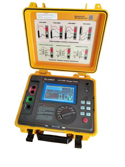
Different types of high-voltage switches, due to the differences in their structure and arc extinguishing medium, there are different methods and standards for insulation resistance testing. For multi-oil circuit breakers, there are numerous insulating components, including bushings, insulating ties, interrupting chambers and insulating oil. In the insulation resistance test, need to use 2500V and above megohmmeter, in the closed state focus on checking the tie rod to the ground insulation, which can sensitively detect whether the tie rod moisture, cracks, whether the surface deposition of pollution and whether the arc path of the penetrating defects such as burns, for the serious insulation defects of the lead line casing can also be reflected. In the breaking state, mainly check the insulation between the breaks and the internal arc extinguishing chamber whether moisture or burns, for the safe operation of the equipment to provide a multi-dimensional guarantee.
Less oil circuit breaker insulation components are mainly porcelain jacket, insulation rod and insulating oil. In the test, the same use of 2500V megohmmeter, closed state to check the insulation of the tie rod to the ground, open state to check the insulation between the breaks as well as the condition of the internal arc extinguishing chamber. For the organic material made of insulated tie rod, the handover test standard stipulates that its insulation resistance at room temperature has strict numerical requirements, different rated voltage corresponds to different standards, for example, the rated voltage in 3 – 15kV, the insulation resistance of the handover test should not be less than 1200MΩ, should not be less than 1000MΩ after the overhaul, should not be less than 300MΩ in the operation of the standards for the judgment of the equipment’s insulation performance. These standards provide a clear basis for judging the insulation performance of the equipment.
Air circuit breaker mainly measures the insulation resistance of its supporting porcelain jacket, generally use 2500V insulation resistance tester, its value should be greater than 5000MΩ, this higher standard ensures the insulation reliability of air circuit breaker in operation. Vacuum circuit breakers and SF6 circuit breakers mainly measure the insulation resistance of primary circuits such as supporting ceramic bushings and tie rods to the ground, and the same 2500V insulation resistance tester is used, and its value should be more than 5000MΩ. In addition, the insulation resistance measurement of auxiliary and control circuits should not be neglected, and it is necessary to take safety measures first, and then use 500V (or 1000V) insulation resistance tester to test, and its value should be more than 2MΩ. For 500kV circuit breaker, it should be measured by 1000V insulation resistance tester, and its value should be more than 2MΩ, and these detailed testing requirements and standards all-roundly guarantee the insulation performance of high voltage switch. These detailed testing requirements and standards guarantee the insulation performance of high-voltage switches in all aspects and lay a solid foundation for the stable operation of power systems.
3.1.2 Contact resistance test: a key indicator of electrical conductivity
Contact resistance is a key indicator of the electrical conductivity of a high-voltage switch, which reflects the degree of contact tightness and electrical conductivity between the switch contacts and between the contacts and the conductor. In the operation of high-voltage switches, excessive contact resistance is like a hidden time bomb, which can bring many serious hazards. Because of the thermal effect of the current through the contact resistance, according to Joule’s law, excessive contact resistance will lead to a large amount of electrical energy being converted into heat, which will cause the temperature of the contact area to rise sharply. This will not only accelerate the oxidation and wear of the contacts, reduce the service life of the contacts, but also may cause serious faults such as contact erosion and welding, and even lead to the failure of the high-voltage switch to open and close the gate, which will threaten the safe and stable operation of the entire power system.
In order to accurately and effectively detect the real situation of contact resistance, a current of more than 100A is usually used during the test. This is because in actual operation, high-voltage switches need to carry large currents, and smaller test currents may not be able to truly reflect the contact state of the contacts in the case of large currents. When the test current is small, the oxidized film, oil and other impurities on the surface of the contacts may hinder the passage of current, making the measured contact resistance value large and unable to accurately reflect the actual contact resistance of the contacts. Using a high current of more than 100A for the test can effectively break through these surface impurities, so that the measurement results are closer to the actual operating contact resistance value, thus providing a reliable basis for judging the electrical conductivity of the high-voltage switch.
3.1.3 Withstand Voltage Test: insulating properties of high-voltage switches
Withstand voltage test is a rigorous test of the insulation performance of high voltage switches. Under the specified test voltage, the frequency AC voltage is continuously applied to the high-voltage switch to observe whether the equipment can withstand the voltage without insulation breakdown or flashover. The test voltage is usually higher than the rated operating voltage of the equipment to simulate the overvoltage conditions that may be encountered during operation. Through the frequency withstand voltage test, the overall performance and reliability of the insulation structure can be effectively checked to ensure that the high voltage switch can maintain a good insulation state under both normal operation and short-time overvoltage conditions.
The test voltage is determined according to the rated voltage of the switch, the insulation structure and other factors. For example, for high voltage switches with a rated voltage of 10kV, the frequency withstand voltage test voltage is usually 42kV; for high voltage switches with a rated voltage of 35kV, the test voltage is usually 95kV. These standards are concluded through a lot of theoretical research and practical experience, and can effectively test the insulation performance of high-voltage switches.
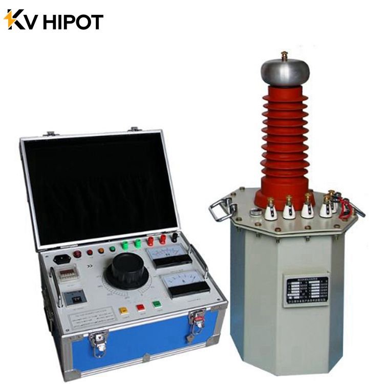
In the test process, it is necessary to operate in strict accordance with the operating procedures. The test personnel should do a good job of division of labor, clear mutual responsibilities, and arrange special people to monitor the site safety and observe the state of the test article. The test specimen should be cleaned up first, and ensure absolute dryness, so as not to damage the test specimen and affect the accuracy of the test results. For large-scale tests, generally should be carried out first, that is, without test specimen voltage to the test voltage, calibration of various meters, adjust the ball gap, to ensure the normal operation of the test equipment and the accuracy of the measurement.
3.1.4 Mechanical Characteristics Test
The mechanical characteristics of the high-voltage switch directly affect the reliability and accuracy of its opening and closing operations, which in turn has an important impact on the safe and stable operation of the power system. Tripping time refers to the time required from the receipt of the opening and closing commands to the complete separation or closure of the switch contacts. Too long tripping time will lead to prolonged fault removal time, which may expand the scope of the fault and pose a serious threat to the stability of the power system; too long closing time may affect the normal power supply restoration speed of the power system, and even lead to system oscillations in some cases. Different types and voltage levels of high-voltage switches, their opening and closing time have strict standard requirements, generally between tens of milliseconds to hundreds of milliseconds.
The opening and closing speed is also an important mechanical parameter. Suitable opening and closing speed can ensure that the contacts are separated or closed quickly during the opening and closing process, effectively quenching the arc, reducing contact burns, and improving the opening and closing capability of the switch. Too fast speed may lead to excessive mechanical impact, damage to equipment parts; too slow speed may not be able to cut off the arc in time, triggering equipment failure.
Simultaneity refers to the consistency of the contact action time of each phase of the three-phase high-voltage switch in the process of opening and closing. If the simultaneity does not meet the requirements, it will lead to three-phase current imbalance, generate additional electromagnetic force and mechanical stress, affect the normal operation of the equipment, and may even trigger the erroneous operation of the relay protection device. Therefore, in the acceptance test, the simultaneity of the high-voltage switch must be strictly detected to ensure that the difference in the action time of each phase is within the permissible range, and the general requirement is that the error in the simultaneity between phases should not be more than a few milliseconds.
3.1.5 Primary high current test: verifying current-carrying capacity
The primary high current test verifies the performance of the high voltage switch when passing high currents. During the test, the high-voltage switch is connected to a specific high-current test circuit to pass a high current that far exceeds the normal operating current. The current-carrying capacity and thermal stability of the switch are evaluated by monitoring various parameters of the switch under high current, such as contact temperature and contact resistance changes. If the switch shows problems such as contact overheating and poor contact during the high current test, this indicates that its current-carrying capacity is insufficient and that the structure or material of the switch needs to be improved.
3.1.6 Secondary relay testing: ensuring reliable protection
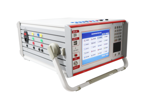
Secondary relay testing is a comprehensive examination of the secondary protection system of a high-voltage switch. By simulating various fault conditions, it tests whether the relay protection device can act accurately, cut off the faulty circuit in time, and protect the safety of the power system. In the testing process, the action value, return value, action time and other parameters of the relay protection device should be accurately measured and adjusted to ensure that they meet the design requirements. At the same time, it is also necessary to check whether the wiring of the secondary circuit is correct and reliable, so as to prevent the protection from malfunctioning or refusing to operate due to the fault of the secondary circuit.
3.1.7 Partial Discharge Test: Discovering Potential Hidden Dangers
In the insulation system of high-voltage switches, when the electric field distribution is not uniform, there are defects inside the insulation material or the local field strength on the electrode surface is too high, it will lead to the occurrence of partial discharge phenomenon. This kind of discharge usually occurs in the air gap inside the insulation, impurities, delamination or tiny bumps on the electrode surface, etc. Although the discharge energy is relatively small, it is like a time bomb hidden in the dark, which will cause serious harm to the insulation performance of the high-voltage switch.
The harm of partial discharge is mainly reflected in the following aspects: first, it will accelerate the aging of insulation. The energy generated by the partial discharge will cause the insulating material to undergo localized thermal decomposition, oxidation and other chemical reactions, which will gradually destroy the molecular structure of the insulating material, leading to a gradual decline in insulation performance. Long-term partial discharge will make the insulation aging speed greatly accelerated, thus significantly shortening the service life of the equipment.
Secondly, partial discharge will reduce the insulation strength. In the discharge process, the generated electrons, ions and other charged particles will continue to impact the insulating material, so that its internal gradually produce small cracks and damage. As the discharge continues, these damages will gradually accumulate, resulting in a continuous reduction of insulation strength. When the insulation strength is reduced to a certain extent, the insulation breakdown may occur under normal operating voltage, resulting in equipment failure.
In addition, serious partial discharge may eventually lead to insulation breakdown, which may lead to equipment short circuit, grounding and other faults. These failures will not only directly lead to equipment damage, the need for repair or replacement of components, increasing maintenance costs and time, but also cause equipment downtime, affecting the normal power supply of the power system, causing great inconvenience to production and life, and may even bring great economic losses .
In addition, the partial discharge process will produce high-frequency electromagnetic radiation, this electromagnetic radiation will cause interference to the surrounding electronic equipment and communication systems. In areas where power facilities are concentrated, such as substations, partial discharges of electrical equipment may interfere with the normal operation of relay protection devices, automation control systems, etc., affecting the stability and reliability of the power system.
In order to discover and accurately assess the partial discharge situation in time, there are various partial discharge test methods commonly used at present. Among them, ultrasonic detection method is to use partial discharge will produce ultrasonic signals this characteristic, through the ultrasonic sensor to capture these signals to detect. The frequency of ultrasonic waves is higher than the audible range of the human ear, usually between 20kHz – 200MHz. The advantages of this method are that the acoustic wave is slow and easy to detect, does not require expensive sensors, and is only sensitive to mechanical vibration, strong resistance to electromagnetic interference.
However, the acoustic signal generated by partial discharge decays quickly in the propagation process, and in gas-insulated metal-enclosed switchgear (GIS), the distance between the sensors can not be more than 1 meter, and a larger number of sensors need to be arranged, with a larger workload of measurement. At the same time, if the sensor is far away from the partial discharge point, there is a possibility that the discharge signal can not be collected, and the method is susceptible to mechanical vibration interference, discharge type identification difficulty, relatively small detection range, it is difficult to quantitative analysis, so it can only be used as an auxiliary means of measurement .
Through the partial discharge test, the insulation condition of the high-voltage switch can be accurately judged according to the test results. If the test results show that the partial discharge amount is within the standard range and there are no abnormal discharge signal characteristics, then it can be assumed that the insulation condition of the high-voltage switch is good and it can continue to operate safely. On the contrary, if the partial discharge exceeds the standard value, or there are abnormal discharge signals, such as abnormal discharge frequency, large discharge amplitude, etc., it indicates that the insulation of the high-voltage switch may have problems, and it is necessary to further analyze the reasons and take corresponding measures, such as overhauling the equipment and replacing the insulating parts, etc., in order to ensure the safe and reliable operation of the high-voltage switch.
3.1.8 Impulse withstand voltage: coping with sudden and powerful shocks
The impact withstand voltage test is an important means of checking the insulation performance of high-voltage switches under the action of lightning overvoltage, operating overvoltage and other impact voltages. In power systems, lightning overvoltages and operational overvoltages are usually very high in amplitude and short in duration, posing a great threat to the insulation performance of high-voltage switches. The impact withstand voltage test is to simulate these impact voltages to check whether the insulation of the high-voltage switch can withstand these sudden and powerful impacts, and to ensure that no insulation damage occurs when it encounters similar situations in actual operation.
The test voltage waveforms used in the withstand voltage test are mainly lightning shock voltage waveforms and operational shock voltage waveforms. The wave front time of lightning impulse voltage wave is very short, generally around 1.2μs, and the half-peak time is around 50μs, which can simulate the overvoltage generated when lightning strikes the power system; the wave front time and half-peak time of operation impulse voltage wave are relatively long, respectively around 250μs and 2500μs, which are used to simulate the overvoltage generated in the process of operation of the power system.
The difference between the impulse withstand test and the IF withstand test mainly lies in the waveform and the action time of the test voltage. The voltage waveform of the IF withstand voltage test is sinusoidal, and the duration of the test is generally 1 min, which is mainly used to assess the insulation performance of the high-voltage switch under long-term IF voltage; while the voltage waveform of the shock withstand voltage test is non-sinusoidal, and the duration of the test is extremely short, which is mainly used to assess the ability of the high-voltage switch to withstand high-amplitude shock voltages within a short period of time. In addition, the test equipment and test method of the shock withstand voltage test are also different from those of the industrial frequency withstand voltage test, and it is necessary to use a specialized shock voltage generator to generate the shock voltage, and to adopt the corresponding measurement and protection devices.
In the testing of high-voltage switches, the impulse withstand voltage test is usually carried out in conjunction with the IF withstand voltage test. The IF withstand voltage test is carried out first to check the insulation performance of the high-voltage switch initially, and then the impulse withstand voltage test is carried out to further assess its insulation capability under impulse voltage. Only if the high voltage switch passes both the IF withstand voltage test and the impact withstand voltage test, can it be considered that its insulation performance meets the requirements and can operate safely and reliably in the power system.
3.1.9 Temperature Rise Test
The temperature rise test is an important test to assess the temperature change of a high-voltage switch under normal operating conditions due to thermal effects, and plays a key role in ensuring the reliability and safety of the equipment over a long period of time. The core principle is based on the fundamental principle of thermodynamics, the law of conservation of energy. When the high-voltage switch is working, electrical energy will be converted into heat energy, which will increase the temperature of the equipment . At the same time, the equipment absorbs heat during the heating process and maintains the temperature equilibrium through heat dissipation. The temperature rise test precisely measures the temperature change of the equipment in order to evaluate its heat dissipation performance and temperature rise condition in depth.
When conducting temperature rise tests, a series of test conditions need to be strictly controlled. The ambient temperature is usually set at the standard test temperature, typically 20°C or 25°C. This stable ambient temperature ensures that the test results are comparable and accurate. The test time is usually a certain length of continuous operation, such as 2 hours, 4 hours or 8 hours, in order to allow the equipment to achieve thermal stability, only in the thermal stability of the data obtained is more representative and reliable. The test load is determined according to the rated load of the equipment, usually a certain percentage of the rated load of the equipment, such as 30%, 50% or full load, the size of the load has a significant impact on the temperature rise of the equipment. The test voltage is determined according to the rated voltage of the equipment, usually a certain percentage of the rated voltage of the equipment, or in accordance with the actual use of the voltage, to ensure that the test conditions in line with the actual operating scenarios. In addition, it is also necessary to install temperature sensors in key parts of the equipment, such as contacts, conductive connections, windings, shells, etc., in order to real-time, accurate recording of temperature changes in the equipment during the test.
The test method for the temperature rise test is as follows: First, the high voltage switch under test is loaded according to the specified load conditions and placed at a constant ambient temperature. The temperature of the device in the initial state is carefully recorded, and the device is then started up so that it begins to operate. During the test, the temperatures of the critical parts of the equipment are measured and recorded at regular intervals until the equipment reaches a thermally stable state. Thermal stability is usually judged by a continuous period of time, the temperature of the key parts of the equipment does not exceed a certain threshold, for example, in 30 minutes, the temperature change does not exceed 1 ° C, the equipment can be considered to have reached a thermally stable state .
In temperature rise testing, a common test circuit is to connect a high-voltage switch to a circuit that simulates actual operation, and control the current and voltage by adjusting the load to achieve the specified test conditions. For example, a high-voltage switch with a rated current of 1000A may be connected to a test circuit capable of supplying 1000A during the temperature rise test, while the test is conducted according to the specified voltage and load conditions.
The key to determining whether the temperature rise passes the test is to compare the calculated temperature rise with the standardized temperature rise limits. Different types of high-voltage switches have different temperature rise limits. For example, for some high-voltage disconnectors, the temperature rise limit value of the contacts may be set at 70K, that is to say, if the difference between the contact temperature minus the ambient temperature does not exceed 70K after reaching the thermal steady state, the temperature rise of the high-voltage disconnectors is considered to be qualified; if it is more than 70K, then it is necessary to analyze the reasons further, which may be poor contact, poor heat dissipation conditions, etc., and the equipment needs to be inspected and improved. Check and improve the equipment.
For high-voltage circuit breakers, the temperature rise limit of the conductive circuit is also clearly defined, generally between 65K – 80K, the specific value depends on the type of circuit breaker, rated current and other factors. When judging whether the temperature rise is qualified, it is necessary to strictly follow the relevant standards and norms to ensure that the high-voltage switch will not cause safety accidents due to overheating in actual operation, so as to ensure the stable operation of the power system.
4 Other Key Test Items Oil Test Equipment and SF6 Gas Test Equipment
Gas and liquid medium test for SF6 gas or insulating oil as insulation and arc extinguishing medium of the high-voltage switch is crucial, SF6 gas purity, moisture content and decomposition products and other indicators directly affect the insulation and arc extinguishing ability. Insufficient purity may lead to a decrease in insulation strength, and high moisture content will freeze at low temperatures, damaging the internal structure of the equipment, while also accelerating the decomposition of SF6 gas, resulting in toxic and hazardous decomposition products, posing a threat to the safety of equipment and personnel. Through the professional gas detection equipment, the SF6 gas indicators to ensure that it meets the relevant standard requirements. For insulating oil, it is necessary to test its breakdown voltage, acid value, moisture content and other parameters to determine whether the performance of insulating oil is good or not, and whether it needs to be replaced or treated.


