In the austere domain of electrical engineering, the AC series resonance test system is a cornerstone, its import as critical as the infrastructure it supports. This article seeks to underscore the vital role of such equipment in the lifecycle of high-voltage applications. We will elucidate its indispensable applications, from the meticulous testing of power plant components to the rigorous validation of transmission lines, underscoring how the stability of our electrical supply hinges on the robustness of these systems.

In the following sections, we will embark on a detailed journey through the significance, application, operation, and fault rectification of the AC series resonance test system—a testament to the system’s silent yet indispensable role in the orchestration of our electrified lives.
1. The importance of AC resonance test system
An AC Resonance Test System is the electrical testing equipment used for conducting AC resonance tests on electrical components and systems. It play a critical role in high voltage applications, serving as a cornerstone for ensuring the integrity and reliability of electrical infrastructure.
AC Resonance Test system provides a high voltage AC source that can test the insulation at or above the normal operating levels. By identifying weaknesses in insulation before they lead to failure, these systems help prevent dielectric breakdown, which can cause catastrophic equipment failures and power outages.
AC Resonance Test Systems can be tuned to the resonant frequency of the test object, which allows for more accurate and effective testing of the insulation properties.
2. AC Resonance Test System Application
AC series resonance system is a essential the commissioning, maintenance, and troubleshooting of electrical system, which is utilized across various sectors within the electrical industry, from power generation to distribution.
Their applications in components and systems are critical for ensuring the reliability and efficiency of electrical power infrastructure. They are applied in different industry sectors such as power plants, electrical grid and production.
Power Generation Plants
Generator Windings: To test the insulation of generator windings, which is essential for the reliability of power generation.
Bus Ducts: For the insulation testing of bus ducts that connect the generator to the transformer.
Step-Up Transformers: Used to test the insulation of transformers that increase the voltage for transmission from the power plant.
Transmission and Distribution
Power Cables: AC series resonance is used extensively for testing the insulation of underground and submarine power cables that transmit electricity over long distances.
Switchgear: To test the insulation and functionality of switchgear which is used to protect and control the power system.
Capacitor Banks: For the testing of capacitor banks used in transmission lines for power factor correction and voltage regulation.
Current and Voltage Transformers: To ensure that these transformers can accurately measure current and voltage in the power system without insulation breakdown.
Energy Sector
Wind Turbine Transformers: For testing the transformers within wind turbines that step up the generated voltage for transmission.
Solar Panel Inverters: To test the insulation of inverters that convert DC produced by solar panels to AC for grid compatibility.
Energy Storage Systems: AC series resonance is applied to test the insulation of components within energy storage systems like large-scale batteries or supercapacitors.
Electric Grid Infrastructure
GIS (Gas-Insulated Switchgear): To perform insulation testing on the compact and efficient GIS used in urban substations.
Circuit Breakers and Disconnectors: For verifying the insulation level and operational integrity under high-voltage conditions.
Protective Relays: Testing the insulation and circuitry of protective relays that safeguard the grid from faults.
Industrial Production Facilities
Industrial Transformers: To test transformers used within industrial facilities for machine operation and plant distribution systems.
Motor Windings: For testing the insulation of high-voltage motors used in heavy machinery and production lines.
Control Panels: To ensure the insulation and functionality of control panels that manage various industrial electrical processes.
Specialized High-Voltage Equipment
HVAC (High-Voltage Alternating Current) Testing Equipment: For the manufacturing and quality assurance of high-voltage testing equipment itself. manufacturing and quality assurance
Research and Development: In R&D facilities, AC series resonance is used to test new high-voltage equipment designs and materials.
3. Testing Operation of AC Dielectric Test Equipment
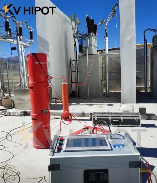
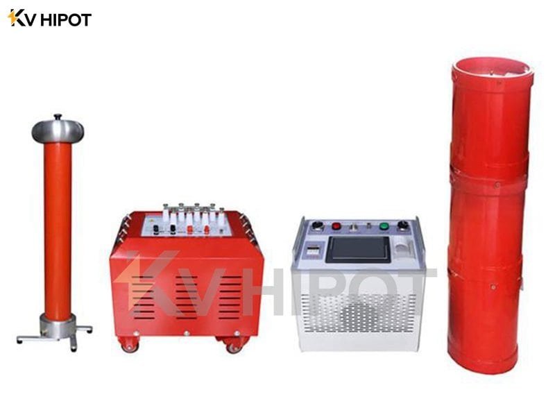
AC withstand voltage series resonance equipment is employed to control the frequency of the power supply, facilitating the resonance of the power reactor and the test capacitor within the test product, enabling the application of high-voltage current. This represents a novel approach to high-voltage experiments and is indicative of current trends in the field. The equipment is comprised of components such as a frequency regulator, voltage regulator, power supply, excitation transformer, reactor, and capacitor voltage divider.
Here is the simple operation step of AC Resonance test system :
- Initial Checks: Perform initial system checks to ensure the test system is functioning correctly. The equipment to be tested is properly connected to the test system. The test objects need to connect cables, terminals, or other necessary components with the equipment
- Setting the parameter to establish resonance: Set the test parameters.This includes setting the desired test frequency, voltage level, and any other specific requirements for the equipment being tested. Slowly increase the frequency to establish resonance within the circuit.
- Boosting Voltage: Gradually increase the voltage to the desired test level while monitoring the condition of the test object.Continuously monitor the test parameters, Continuously monitor the test parameters and the condition of the test object.
- Record and analyze : Record the test results for analysis and documentation.Analyze the recorded test results to determine the performance and reliability of the equipment. Compare the measured values with the specified limits or standards to assess the equipment’s compliance.
- Take Necessary Actions: Based on the test results, take appropriate actions, such as maintenance, repair, or further testing, depending on the specific requirements and findings.
If you want to know more about the specific operation details, please review the manufacturer KV Hipot Power Equipment Co.,ltd manual for both the test system and the equipment to be tested.
4. Common faults and trouble methods for AC Resonance Test Set
For users of this equipment, the primary concern often revolves around potential issues that may arise and how to address them. Let’s delve into common problems encountered during series resonance and their respective solutions:solutions
1) Fan Failure:
Issue: The fan does not start.
Possible Causes:
(1) Emergency stop, fault maintenance, detuned maintenance, without pressing the “fault reset” button.
(2) Excessive internal temperature leading to thermal issues in power components.
Solution:
(1) Ensure the equipment is not in an emergency stop state, perform necessary fault maintenance, and press the “fault reset” button.
(2) Allow the instrument to cool by turning off the power supply for about 30 minutes. Afterward, restart the instrument by pressing the “reset” button on the instrument panel.
2) Failure to Complete Active Tuning and Locate Resonance Point:
Issue: Tuning curve appears as a straight line, and the instrument reports no resonance point after setting the resonance
Possible Causes:
Poor equipment grounding, errors in experimental circuit wiring, or open circuits in the equipment or instrument.
Solution:
(1) Verify the reliability of the equipment grounding and check for disconnected ground connection lines.
(2) Examine the on/off status of the excitation transformer’s high and low voltage coils (including resistance values).
(3) Inspect the on/off status of each reactor’s windings (including resistance values of each winding ).
(4) Review the status of the signal line connections in the power divider (both high and low voltage).
(5) Check the on/off status of the high and low voltage capacitor arms in the voltage divider.
(6) If no resonance point is achieved, inspect the compensation capacitor.
3) Failure to Reach Experimental Voltage:
Phenomenon
(1) The tuning curve is a straight line with lower spikes.
(2) The primary voltage is higher during the experiment, but the high voltage is lower and doesn’t reach the desired experimental voltage, despite the primary voltage being in excess of the extra voltage.
Possible Causes:
(1) Mismatch between the reactor and test piece capacity, preventing precise resonance point detection.
(2) High pilot loss, resulting in an excessively low system Q value.
(3) Low high-voltage output voltage from the power excitation transformer.
(4) Excessive length of the high-voltage connection line or an incorrect high-voltage discharge corona line.
Solution:
(1) Increase circuit capacity by adding compensation capacitors and connecting them to the experimental circuit.
(2) Introduce additional reactors in series to enhance circuit inductance.
(3) Raise the output voltage of the excitation transformer.
(4) Dry the test article, enhance its insulation strength, and reduce circuit losses.
(5) In cases of higher voltage output equipment, opt for high-voltage discharge corona lines or shorter high-voltage output lines, generally not exceeding 5 meters in length.