


What Is Transformer Tan Delta?
Tan Delta, also known as dielectric dissipation factor, is a measure of the energy lost in an insulation system when AC voltage is applied.
Ideal insulation behaves like a capacitor and carries only capacitive current. Real insulation also carries a small resistive or loss component caused by polarization, moisture, contamination, aging and other dielectric processes.
The loss angle is designated by δ, and its tangent can be expressed approximately as:
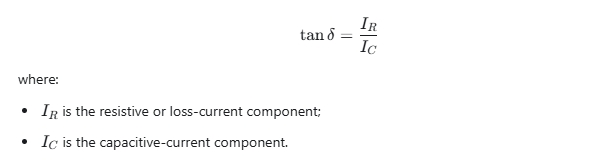
A lower Tan Delta generally indicates lower dielectric loss. An elevated or increasing value may indicate deterioration, but it should not be interpreted without considering temperature, test voltage, frequency, capacitance, historical data and other diagnostic results.
Tan Delta, Dissipation Factor and Power Factor
The terms Tan Delta, dissipation factor and power factor are often used interchangeably in transformer field testing, especially when the measured loss is small.
They are closely related but not mathematically identical:
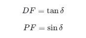
At the low loss angles normally encountered in healthy transformer insulation, the numerical difference between PF and DF is very small. Nevertheless, test reports should identify which quantity the instrument displays.
A comparison is only meaningful when the same parameter, test mode, frequency, voltage and temperature basis are used.
What Parts of a Transformer Are Measured?
A complete transformer Tan Delta test does not produce only one value. Different test connections isolate different sections of the insulation system.
For a two-winding transformer, the principal insulation components are commonly represented as:
- CH: high-voltage winding to ground
- CL: low-voltage winding to ground
- CHL: high-voltage winding to low-voltage winding
For a three-winding transformer, additional insulation components may include:
- CT: tertiary winding to ground
- CHT: high-voltage winding to tertiary winding
- CLT: low-voltage winding to tertiary winding
The exact notation used by a test instrument or utility procedure may differ. Always confirm the definitions used in the applicable test form.
Transformer bushings may also be tested separately:
- C1: main insulation between the bushing conductor and test tap
- C2: insulation between the test tap and grounded flange
C1 and C2 are different insulation systems and normally have different ratings and test-voltage limitations.
What Are GST, GSTg and UST?
The test mode determines which current paths are measured and which are excluded.
| Test mode | Basic function | Typical application |
|---|---|---|
| GST | Measures all current returning through ground | Combined insulation-to-ground measurement |
| GSTg or GST-Guard | Measures the selected ground path while excluding guarded current | Isolating one winding-to-ground insulation section |
| UST | Measures current between two ungrounded terminals | Inter-winding insulation or bushing C1 |
| UST with guard | Measures a selected ungrounded current path while excluding additional paths | Complex multi-terminal equipment |
GST: Grounded Specimen Test
In GST mode, one terminal of the insulation under test is effectively grounded. The test set measures current returning through ground.
GST is useful when all relevant insulation paths to ground are intended to be included in the result.
GSTg: Grounded Specimen Test with Guard
GSTg uses a guard circuit to exclude unwanted leakage or insulation paths from the measurement.
For example, when measuring the high-voltage winding insulation to ground, the low-voltage winding may be connected to the guard circuit so that its current does not contribute to the measured CH result.
UST: Ungrounded Specimen Test
UST measures an insulation path between two terminals that are isolated from ground.
It is commonly used for:
- High-voltage-to-low-voltage winding insulation
- Bushing C1 insulation
- Other insulation sections with an accessible measurement terminal
The terms “forward connection” and “reverse connection” used by some test-set manufacturers should not automatically be treated as exact synonyms for GST and UST. The correct mode must be determined from the actual current path and the instrument wiring diagram.
Applicable Transformer Tan Delta Standards
For field testing of liquid-filled power transformers, a principal reference is IEEE C57.152-2025, IEEE Guide for Diagnostic Field Testing of Liquid-Filled Power Transformers, Regulators, and Reactors.
The guide describes field diagnostic measurements and emphasizes two important principles:
- Several diagnostic tests should be interpreted together.
- Transformer manufacturers’ acceptance criteria should also be consulted and may take precedence over general guidance.
For transformer bushings, relevant references include:
- IEC 60137:2017, which specifies characteristics and tests for insulated bushings above 1,000 V;
- IEEE C57.19.00-2023, which covers general requirements and test procedures for certain power apparatus bushings.
IEC 60076-3:2013+A1:2018 addresses transformer insulation levels, dielectric tests and external clearances. Its dielectric withstand levels should not be confused with the voltage used for a field Tan Delta diagnostic test.
Standards provide a test and interpretation framework. They do not justify applying one universal Tan Delta limit or one universal test voltage to every transformer.
Is There a Universal Acceptable Tan Delta Value?
No single percentage should be used as a pass/fail limit for every transformer.
Online articles sometimes state that a value below 0.5%, 0.7% or 1.0% is always acceptable. Such a rule ignores major differences between:
- New and in-service equipment
- Winding insulation and bushing insulation
- Mineral-oil, ester and other insulation systems
- OIP, RIP and RIS bushings
- Test temperatures
- Test voltages and frequencies
- Transformer designs and voltage classes
- Factory, commissioning and maintenance measurements
A sound evaluation should use the following hierarchy:
- Transformer or bushing manufacturer’s limits
- Factory test data
- Commissioning baseline data
- Previous results from the same insulation section
- Comparison between similar phases or identical units
- Applicable utility, customer or industry requirements
- Supporting diagnostic measurements
An isolated Tan Delta value is less informative than a consistent trend.
Transformer Tan Delta Test Preparation
1. Review the Transformer Information
Before testing, record:
- Manufacturer and serial number
- Rated power and voltage
- Winding configuration and vector group
- Number of windings and neutral arrangement
- Bushing type and test-tap rating
- Insulating-liquid type
- Previous Tan Delta and capacitance results
- Manufacturer-recommended test voltage
- Any recent repair, oil processing or bushing replacement
The test sequence should be prepared before leads are installed.
2. De-Energize and Isolate the Transformer
The transformer must be taken out of service and isolated from all energy sources according to the approved lockout/tagout procedure.
Disconnect external conductors that may affect the measurement, which may include busbars, power cables, neutral-ground connections, surge arresters, potential transformers and connected auxiliary equipment. The exact disconnections depend on the transformer design and the required measurement.
3. Discharge and Ground All Windings
After isolation:
- Verify the absence of voltage.
- Discharge each winding.
- Apply temporary protective grounds.
- Maintain grounds until the approved test connection is ready.
- Reapply grounds before changing leads.
Transformer windings and bushings can retain hazardous charge after testing.
4. Short Each Winding Group
All line and neutral terminals belonging to the same winding should normally be shorted together for an overall winding-insulation measurement.
Shorting the terminals treats the winding as one electrical terminal, reduces the influence of winding inductance and produces a repeatable insulation measurement.
5. Clean and Inspect the Bushings
Dust, salt, oil, condensation and moisture on the bushing surface can create leakage current that raises or destabilizes the result.
Before testing, clean and dry the surface, inspect for cracks or tracking, check for oil leakage and inspect the test tap.
6. Record Environmental Conditions
Record at least:
- Ambient temperature
- Transformer top-oil temperature, when available
- Relative humidity
- Weather condition
- Test frequency
- Applied voltage
Do not compare results taken at significantly different temperatures without an approved correction or interpretation method.
7. Ground the Test Set
Connect the test-set protective ground directly to the station ground grid or another approved low-impedance grounding point.
The DX8000 includes a ground-detection function. It is recommended that this protection remain enabled. Ground detection supports safe operation but does not replace visual inspection and verification of the ground connection.
How to Select the Test Voltage
The test voltage must be high enough to provide a stable measurement but low enough to remain within the permissible diagnostic voltage for the insulation section.
A 10 kV test voltage is widely used for suitable high-voltage transformer insulation and bushing C1 measurements, However, 10 kV must not be applied automatically to every test object.
Consider:
- Winding voltage rating
- Insulation level
- Bushing and test-tap rating
- C1 or C2 insulation section
- Transformer manufacturer instructions
- Customer test procedure
- Test-set output capacity
- Previous test voltage used for trending
A bushing C2 test tap may have a much lower permissible test voltage than the bushing’s main C1 insulation. Applying the C1 test voltage to C2 without confirmation can damage the bushing.
If the allowable voltage is uncertain, stop and obtain the manufacturer’s value before energizing the test circuit.
Two-Winding Transformer Test Sequence
The following matrix illustrates the insulation sections commonly measured on a two-winding transformer. Instrument terminology and lead assignment must be confirmed against the test-set manual.
| Test objective | Energized winding | Other winding | Typical result |
|---|---|---|---|
| HV to LV | HV | LV connected to measuring input and isolated from ground | CHL, normally UST |
| HV to ground with LV guarded | HV | LV connected to guard | CH, normally GSTg |
| HV to LV and ground | HV | LV grounded | CH + CHL, GST |
| LV to ground with HV guarded | LV | HV connected to guard | CL, normally GSTg |
| LV to HV and ground | LV | HV grounded | CL + CHL, GST |
A practical sequence is:
- Short all HV terminals together.
- Short all LV terminals together.
- Isolate the neutral if required by the approved procedure.
- Connect the instrument ground.
- Perform the HV-to-LV UST measurement.
- Perform the HV-to-ground measurement.
- Perform the LV-to-ground measurement.
- Confirm that the measured combinations are electrically consistent.
- Discharge all windings before changing connections.
The DX8000 manual provides reference connections identified as CHG + CHL and CLG + CLH. These are combined insulation measurements. The operator should verify which current paths are included before comparing them with a separately measured CH, CL or CHL value.
Three-Winding Transformer Test Sequence
A three-winding transformer requires additional measurements because every winding has insulation to ground and insulation to the other windings.
The DX8000 reference wiring includes combined measurements such as:
CHG + CHL, with the tertiary appropriately shielded or guarded;CLG + CLT, with the HV winding appropriately shielded or guarded;CTG + CHT, with the LV winding appropriately shielded or guarded.
Because multi-winding measurements can include several parallel insulation paths, the test sheet must record:
- Winding energized
- Winding connected to Cx
- Winding grounded
- Winding guarded
- Test mode
- Included insulation components
- Applied voltage and frequency
A result should never be labeled only “transformer Tan Delta.” It should identify the actual insulation section measured.
Step-by-Step Test Procedure Using a KV-6000A Tan Delta Tester
The following workflow applies the operating logic described in the DX8000 manual. Always confirm the current instrument interface and supplied wiring diagram.
Step 1: Inspect the Test Set
Check the power cable, protective earth lead, HV cable, Cx cable, cable shielding, connectors, emergency stop and test-area barriers.
Use the test cables supplied or approved for the instrument. Different cables may introduce additional capacitance, leakage or shielding errors.
Step 2: Connect Protective Ground
Ground the test set before connecting the HV lead.
Do not disable the ground-detection function simply to bypass a warning. Investigate the grounding connection and, when using a generator, verify its neutral-ground arrangement.
Step 3: Connect the Transformer
Connect the HV, Cx, guard and ground leads according to the selected insulation section.
Keep the HV connection separated from grounded conductors. The test-lead shield is not interchangeable with the main conductor; follow the wiring diagram for the selected forward, reverse or shielded measurement.
Step 4: Select the Test Mode
Choose the mode corresponding to the required current path, such as forward connection, reverse connection, external HV, external standard, GST-equivalent grounded measurement, guarded measurement or UST-equivalent inter-winding measurement.
Do not select a mode only by its name. Confirm what the instrument measures in that mode.
Step 5: Set Voltage and Frequency
Enter the approved test voltage and frequency.
For substations with strong power-frequency interference, a frequency-conversion test set can measure at frequencies offset from the interference source. The DX8000 uses variable-frequency measurement and digital interference rejection. Record the actual measurement frequencies in the report.
Step 6: Start the Test
Verify that personnel are outside the high-voltage area, then start the test. The DX8000 automatically raises the voltage, changes frequency as configured, acquires the data and displays the result.
Monitor output voltage, test current, Tan Delta, capacitance, frequency and protection messages. Stop the test if there is abnormal noise, discharge, unstable current or any unsafe condition.
Step 7: Save the Result
Record the test object, connection, mode, voltage, frequency, Tan Delta, capacitance, current, temperature, humidity, date, time and operator. The DX8000 supports internal data storage, printing and USB export.
Step 8: Reduce Voltage and Discharge
Allow the instrument to complete its voltage-reduction and discharge sequence. Confirm that the output has returned to zero, discharge the tested insulation section, apply a temporary ground and only then change the leads.
How to Interpret Transformer Tan Delta Results
Compare With Previous Results
Trend analysis is normally more valuable than applying a generic numerical limit. Use the same test connection, voltage, frequency, temperature basis and lead configuration.
A gradual increase may indicate progressive aging, contamination or moisture. A sudden change requires investigation of both the insulation and the test conditions.
Evaluate Capacitance Together With Tan Delta
| Observation | Possible significance |
|---|---|
| Tan Delta increases while capacitance remains stable | Moisture, contamination, aging or surface leakage |
| Capacitance changes significantly | Internal movement, damaged grading layers, open or shorted condenser layers, or connection error |
| Tan Delta and capacitance both change | Significant insulation change or incorrect connection |
| Value is unstable | Interference, poor contact, dirty surface, incorrect guard or active discharge |
| One phase differs from comparable phases | Localized insulation or bushing problem |
These are diagnostic indications, not automatic failure conclusions.
Consider Temperature
Dielectric loss is temperature-dependent. Use manufacturer correction data, an approved test-set correction method or results obtained at comparable temperatures. Avoid applying a universal correction multiplier to every insulation system.
Use Supporting Tests
An abnormal result may justify additional testing, such as:
- Insulation resistance and polarization measurements
- Oil moisture analysis and dissolved gas analysis
- Oil dielectric dissipation factor
- Bushing C1 and C2 tests
- Excitation current
- Transformer turns ratio
- Winding resistance
- Dielectric frequency response
- Partial-discharge investigation
IEEE C57.152-2025 emphasizes interpreting several diagnostic measurements together rather than diagnosing a transformer from one test alone.
Common Testing Problems
Ground Detection Failure
Check the test-set ground, station ground, clamp condition and generator neutral grounding. A floating power source may prevent the ground-detection circuit from being satisfied.
Test Signal Is Too Low
Possible causes include a disconnected HV or Cx lead, incorrect mode, poor terminal contact, very small test capacitance or incorrect external-HV configuration.
Test Signal or Current Is Too High
Possible causes include excessive test-object capacitance, incorrect connection, a short circuit, excessive voltage or damaged insulation. Do not repeatedly restart the test without identifying the cause.
Tan Delta Is Unstable
Inspect bushing cleanliness, condensation, lead movement, shield connection, Cx contact, grounding, nearby energized equipment and frequency selection.
Why Frequency Conversion Matters in Substation Testing
Measurements in energized substations may be affected by strong 50 Hz or 60 Hz electromagnetic fields. A frequency-conversion tester can apply a controlled frequency away from the dominant interference and use digital processing to improve measurement stability.
This is useful for high-capacitance test objects, locations close to energized busbars, generator-powered field testing and measurements intended for long-term trending.
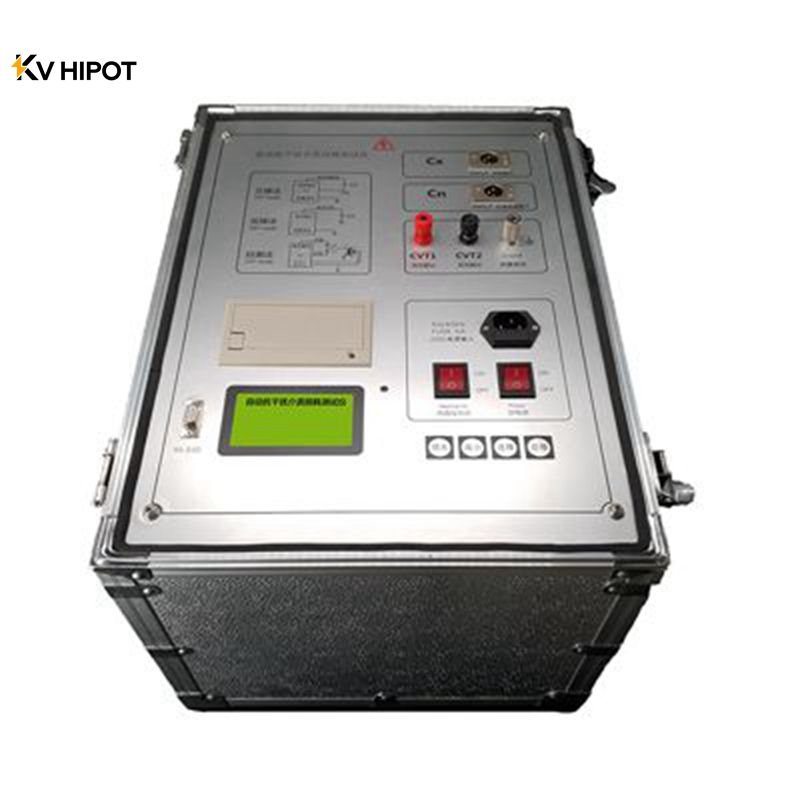
The DX8000 integrates a variable-frequency power source, test transformer, standard capacitor and measurement bridge. It also provides automatic voltage control, ground detection, protection functions, data storage and printing.
What to Look for in a Transformer Tan Delta Tester
Before selecting a test set, confirm:
- Maximum output voltage
- Maximum test current and capacitance
- Measurement accuracy
- Frequency-conversion range
- GST, GSTg and UST capability
- Forward and reverse measurement capability
- Internal and external HV support
- Ground detection and automatic discharge
- Overvoltage and overcurrent protection
- Emergency stop
- Data storage, printing and export
- Test-lead shielding
- Suitability for two- and three-winding transformers
- Suitability for bushing C1 and C2 measurements
- Calibration and after-sales support
Frequently Asked Questions
Can a Transformer Tan Delta Test Be Performed While Energized?
No. A conventional offline transformer Tan Delta test requires the transformer to be de-energized, isolated, discharged and properly grounded.
Is 10 kV Always Used?
No. Although 10 kV is common for suitable high-voltage insulation sections, the permissible voltage depends on the transformer winding, bushing test tap, insulation rating, manufacturer instructions and test objective.
What Is the Difference Between Tan Delta and Insulation Resistance?
Insulation resistance uses DC voltage to assess leakage resistance. Tan Delta uses AC voltage to evaluate dielectric losses and capacitance. The tests provide different information and are often more useful when interpreted together.
Why Must All Terminals of One Winding Be Shorted Together?
Shorting the terminals allows the winding to behave as one test electrode and produces a repeatable overall insulation measurement.
Why Should Capacitance Be Recorded?
Capacitance helps identify physical changes in the insulation structure. A significant capacitance change may reveal a condition that is not evident from Tan Delta alone.
Can One Limit Be Used for Every Transformer?
No. Assess the result using manufacturer limits, baseline data, historical trends, temperature, voltage, frequency, insulation type and supporting diagnostic tests.
What Causes a High Tan Delta Result?
Possible causes include moisture, contamination, insulation aging, oil deterioration, carbonized paths, surface leakage, damaged bushings or an incorrect test connection.
Can Tan Delta Predict Remaining Transformer Life?
Not by itself. It is a condition indicator, not a direct remaining-life calculation.
Conclusion
Transformer Tan Delta testing is one of the most useful offline methods for evaluating winding and bushing insulation. Its reliability depends on correct isolation, grounding, winding configuration, test mode, voltage selection and result comparison.
Do not judge a transformer from one percentage alone. Record Tan Delta and capacitance together, compare equivalent insulation sections under consistent conditions, review historical trends and use other diagnostic tests to confirm abnormal findings.
For help selecting a Tan Delta tester or confirming a test configuration, provide:
- Transformer rated voltage and capacity
- Number of windings
- Vector group and neutral arrangement
- Bushing type
- Required test voltage
- Available factory or previous test data
Our technical team can recommend a suitable test configuration and Tan Delta test system for laboratory, commissioning or substation maintenance applications.



 English
  ไทย
ไทย  Tiếng Việt
  العربية
  Русский
  Italiano
  Español
  한국어
한국어  Português do Brasil
  Français
  Español de México
  Português
  Türkçe
  Čeština
  Español de Argentina
  Slovenčina
  Dansk
Dansk  Polski
  Deutsch
  Ελληνικά
  O‘zbekcha
  Bahasa Indonesia
  Română