Sudden grid failures cost money and ruin equipment. You cannot see the hidden insulation damage inside your transformers. A partial discharge detector finds this invisible danger early. A partial discharge detector is a testing device that identifies tiny electrical sparks inside high-voltage insulation. It uses sensors to capture ultrasonic waves, ground voltages, and electromagnetic signals. This tool helps engineers find insulation defects months before a complete power failure happens. Ignoring tiny sparks inside your switchgear will destroy your entire power system. Let us explore the invisible forces that threaten your equipment right now.
What is partial discharge in electrical equipment?
Microscopic cracks in solid insulation grow silently over time. This slow decay causes unexpected explosions. You need to understand these tiny sparks to save your grid. Partial discharge is a small electrical spark that bridges only a part of the insulation between two conducting metals. It happens inside tiny air voids in solid insulation or on the surface of dirty insulators. These small sparks slowly eat away the material until the equipment completely fails.
The hidden causes of insulation failure
I see many ruined transformers in my work. The damage almost always starts with a tiny air void. Cast-resin transformers have a solid insulation structure. Sometimes, a tiny air bubble gets trapped inside the resin during manufacturing. Air is weaker than solid resin. The high voltage easily breaks the air. This causes a small spark. We call this internal partial discharge.
Surface tracking on insulators
Another common problem happens outside the insulation. Dirt, moisture, and dust stick to the surface of switchgear insulators. The high voltage pushes electricity across this dirty layer. This creates a surface tracking discharge. The spark burns a carbon path into the plastic. The carbon path conducts electricity. It grows longer every day.
| Discharge Type | Where It Happens | Main Causes | Failure Speed |
|---|---|---|---|
| Internal Discharge | Inside solid insulation | Air voids, trapped bubbles | Slow and hidden |
| Surface Tracking | Outside the insulator | Dirt, moisture, carbon dust | Medium to fast |
| Corona Discharge | Sharp metal edges | Damaged wires, bad joints | Slow |
You must catch these sparks early. A partial discharge detector acts like a medical tool. It hears the sickness inside the machine before the machine dies.
How does a partial discharge detector work?
Finding invisible sparks in a closed metal cabinet seems impossible. Guessing the condition wastes your maintenance budget. A partial discharge detector gives you real data instantly. A partial discharge detector captures the physical emissions created by tiny electrical sparks. The device uses external or built-in sensors to detect high-frequency acoustic sounds, electromagnetic waves, and transient ground voltages. The software then analyzes these signals to show the exact discharge intensity and pulse frequency.
Capturing the invisible signals
Every small spark inside your equipment releases energy. This energy travels out in different forms. It creates a tiny sound wave. It also creates a fast electromagnetic pulse. I always explain this to power contractors using a thunderstorm example. When lightning strikes, you see the flash and hear the thunder. A partial discharge detector does the exact same thing for high-voltage cabinets.
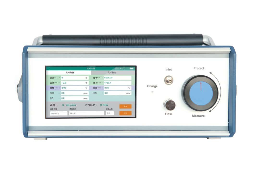
How the KVJF-8000 processes data
KV Hipot type KVJF-8000 partial discharge tester is a perfect example of this technology. It has built-in sensors that listen to these tiny sounds and watch for the voltage pulses. The machine captures the signals. It draws a map on its screen. This map is called a PRPD pattern. The PRPD pattern shows exactly when and how often the sparks happen during the AC power cycle.
| Detector Component | Function | Data Output |
|---|---|---|
| Ultrasonic Sensor | Hears acoustic sound waves | dBμV values |
| TEV Sensor | Feels ground voltage pulses | dBmV values |
| LCD Screen | Shows real-time PRPD charts | Visual graphs |
| Alert System | Makes warning sounds | Audio beeps |
The detector translates complex physics into simple green, yellow, and red numbers. You just hold the device near the cabinet. The machine tells you if the switchgear is safe or dying.
What is the difference between TEV, AE, and UHF sensors in PD testing?
Using the wrong sensor hides serious equipment defects. You will miss critical warning signs and face a blackout. You must match the right sensor to the right electrical problem. TEV sensors measure transient earth voltages on metal switchgear surfaces. AE sensors listen for high-frequency ultrasonic sounds from surface discharges. UHF sensors detect electromagnetic waves inside sealed GIS tanks. Each sensor targets a specific physical emission from the partial discharge event.
Matching sensors to electrical assets
I always tell my customers to look at their equipment first. A switchgear cabinet needs different testing tools than a long power cable. The KVJF-8000 uses multiple sensor ports to solve this problem. You plug in the right sensor for your job.
TEV, AE, and UHF functions
TEV sensors are great for metal-clad switchgear. When a spark happens inside, it creates a fast voltage spike. This spike travels along the metal box. The TEV sensor touches the outside metal. It measures this spike. AE sensors act like microphones. They hear the ultrasonic crackling noise of a spark. I use AE sensors to find surface tracking on dirty insulators or loose connections. UHF sensors are the only way to test a GIS. The thick metal GIS tank traps all sounds and ground waves. The spark creates high-frequency radio waves. The UHF sensor looks through the GIS viewing window to catch these radio waves.
| Sensor Type | Emission Detected | Best Equipment to Test | Key Advantage |
|---|---|---|---|
| TEV | Electromagnetic surface pulses | Metal-clad Switchgear | Detects internal defects easily |
| AE | High-frequency sound waves | Transformers, Open air gaps | Pinpoints exact spark locations |
| UHF | Radio waves | GIS | Ignores outside corona noise |
| HFCT | Pulse currents | Power Cables | Clips onto grounding wires |
Using the correct sensor gives you accurate data. It stops background noise from ruining your test.
Why is non-intrusive PD testing important for modern power grids?
Shutting down power lines for testing makes customers angry. Reactive maintenance costs too much money. Non-intrusive testing lets you check equipment while the power stays on. Non-intrusive PD testing shifts the power sector from reactive to predictive maintenance. Engineers test live equipment without causing power outages. They find the first microscopic signs of insulation failure and fix the problem months before a catastrophic flashover destroys the grid.
The shift to predictive maintenance
Old power grids used a run-to-failure strategy. Engineers waited for a transformer to explode. They replaced it later. This method caused massive blackouts. It wasted millions of dollars. Today, we use condition-based monitoring. We check the health of the equipment while it works. A partial discharge event is the earliest warning sign of a breakdown.
Keeping the lights on
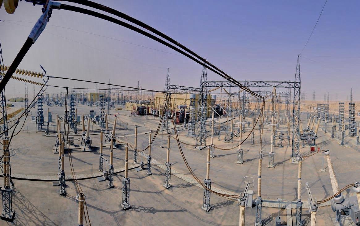
Non-intrusive testing means you do not touch the live wires. You do not turn off the power. I walk into a substation with my portable detector. I hold the sensor against the outside of the metal cabinet. The machine measures the internal sparks. The customers never lose their electricity. The factory keeps running.
| Maintenance Strategy | Action Taken | Cost Level | Power Outage Required |
|---|---|---|---|
| Reactive | Fix equipment after it explodes | Extremely High | Yes |
| Scheduled | Turn off power every year | High | Yes |
| Predictive | Monitor live equipment health | Very Low | No |
This technology guarantees grid stability. You order spare parts early. You schedule repairs only when the data shows real danger. A partial discharge detector finds hidden insulation damage early. Using TEV, AE, and UHF sensors ensures safe predictive maintenance that stops sudden power grid failures.