Why do we use a 5 kV DC Megger test on a 22 kV AC cable?
Are you unsure about the right test for your 22 kV cables? Using the wrong method can miss critical faults and lead to expensive failures down the line.
A 5 kV DC Megger test is used on a 22 kV AC cable for a very specific purpose: testing the integrity of the outer sheath or jacket. It is not suitable for testing the cable’s primary insulation. For the main insulation, a VLF (Very Low Frequency) or AC Hipot test is necessary to apply the correct electrical stress and reliably find defects.
You might be wondering why one test is perfect for one part of the a cable but wrong for another. Understanding this difference is key to ensuring the long-term health and safety of your power systems. We need to look closer at what each part of the cable does and how different electrical tests affect it. Let’s explore why DC is the standard for sheath testing and why it’s a poor choice for modern cable insulation.
Why is DC used for cable outer sheath testing?
Confused about why a DC test is right for the sheath but wrong for the main insulation? This confusion can lead to improper testing and unreliable results.
We use DC voltage for outer sheath testing because the sheath is a simple, non-conductive layer designed for mechanical and moisture protection. A DC withstand test is a straightforward method to check for physical breaches like pinholes or cracks. It confirms the sheath’s basic insulating job without causing harm.
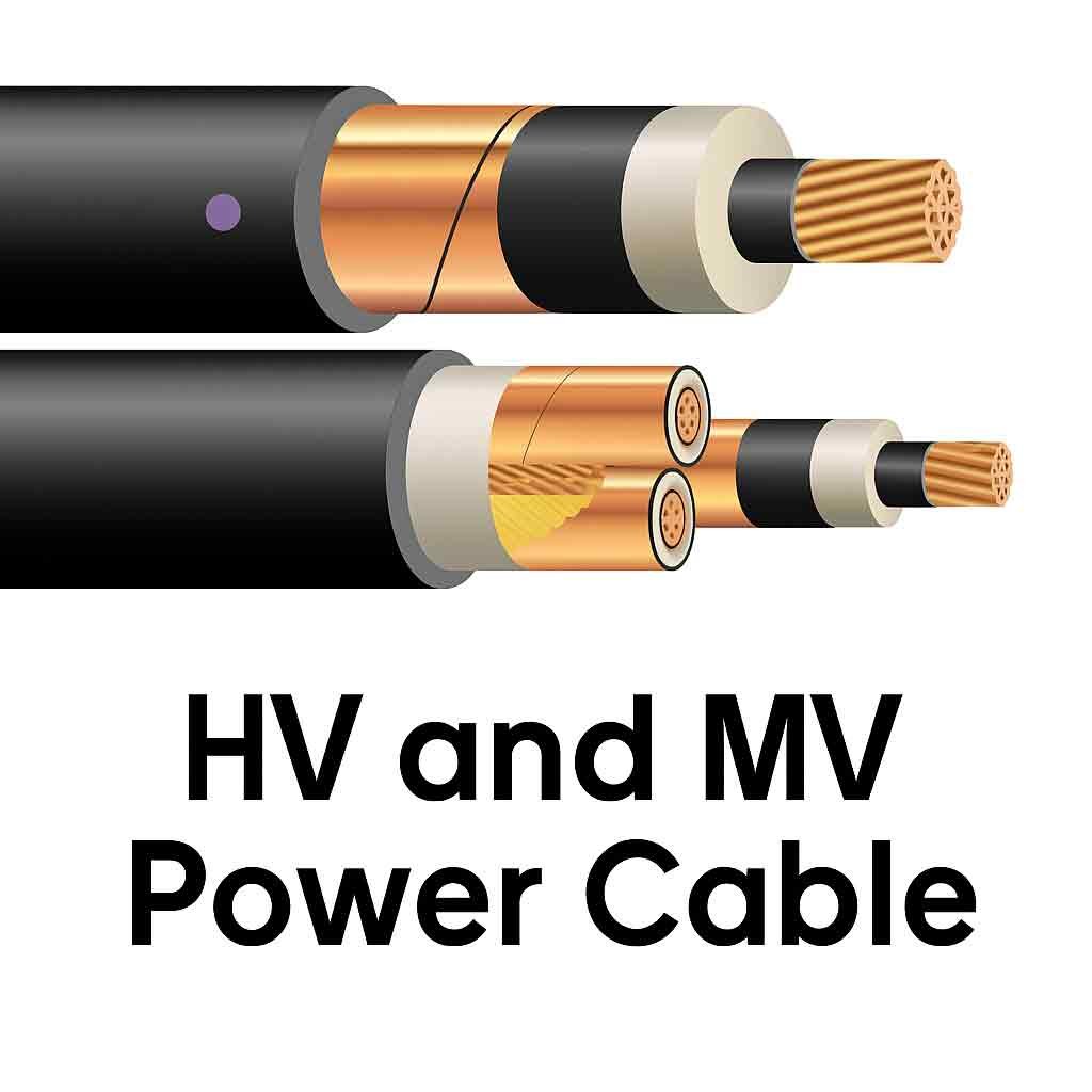
The outer sheath of a high-voltage cable acts as its first line of defense. Its main job isn’t to handle high electrical voltage but to protect the internal components, especially the metallic shield and primary insulation, from the outside world. This includes protection from moisture, chemicals, and physical damage during and after installation. A breach in the sheath can allow water to reach the metallic shield, leading to corrosion and eventually insulation failure. A DC sheath test is a simple quality control check.
According to the IEC 60502-2 standard, we apply a DC voltage, often 10 kV for 1 minute, between the cable’s metallic shield and an external ground. If there are no holes or cracks, the sheath holds the voltage. If there is a fault, current will flow, and the test will fail, alerting us to the damage. This simple pass/fail test is highly effective for its specific purpose.
| 기능 | DC Sheath Testing | AC/VLF Hipot Testing |
|---|---|---|
| Component Tested | Outer Sheath/Jacket | Primary Insulation (e.g., XLPE) |
| Primary Goal | Verify mechanical integrity (no holes/cracks) | Find electrical weaknesses (water trees, voids) |
| Voltage Type | Direct Current (DC) | Alternating Current (AC or VLF) |
| Typical Test Voltage | 10 kV DC (as per IEC 60502-2) | 22 kV to 38 kV rms (for a 22 kV cable) |
| Why it Works | Simple voltage withstand for a simple insulator | Simulates service conditions to stress defects |
Should HV (6-35kV) cable pressure tests use AC or DC?
Choosing between AC and DC for your main insulation tests is a critical decision. Making the wrong choice can hide serious problems or even damage your cable.
For modern high-voltage cables with XLPE insulation, you must use an AC test. DC testing is an outdated method for this type of cable. It can cause a damaging effect called “space charge,” which can lead to future failures after the cable is returned to service. Standards from the IEEE and IEC strongly recommend AC or VLF AC tests.
Using DC voltage to test modern XLPE (Cross-Linked Polyethylene) insulation is a bad idea. While it was the standard for old paper-insulated cables, it is harmful to modern dielectric materials. When you apply a high DC voltage to an XLPE cable, electrical charges can become embedded deep inside the insulation. This is called “space charge.” These trapped charges do not disappear when the test is over. Later, when you energize the cable with its normal AC voltage, the trapped DC charges create points of extremely high electrical stress. These stress points can weaken the insulation and cause it to fail prematurely.
So, the DC test itself can be the cause of a future fault. AC testing, on the other hand, mimics the cable’s normal operating conditions. It stresses the insulation in the way it was designed to be stressed, revealing real weaknesses without creating new ones.
| Test Method | Effect on XLPE Insulation | Risk to Cable Health | Recommendation |
|---|---|---|---|
| DC Hipot Test | Creates harmful “space charge” and poor stress distribution | High. Can lead to in-service failure caused by the test. | Not Recommended (Obsolete) |
| AC (VLF) Hipot Test | Safely simulates AC service stress to find true defects. | Low. Does not create space charge. | Highly Recommended |
What is the VLF test for MV cables?
You need an effective AC test, but standard power-frequency test sets are massive. These units are often too heavy and impractical for most field work.
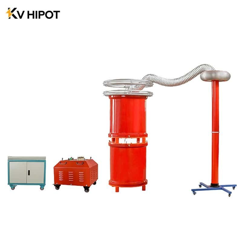
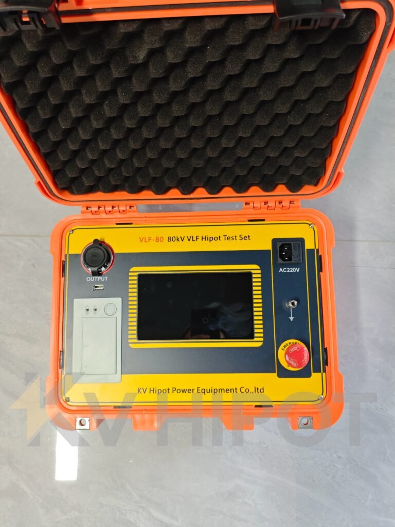
A VLF (Very Low Frequency) test is a special type of AC withstand test. It uses a much lower frequency, typically 0.1 Hz instead of the standard 50 or 60 Hz. This simple change drastically reduces the power and size of the test equipment, making it very portable.
The science behind VLF testing is straightforward. The power required to test a cable is directly related to the frequency of the voltage. The formula is P = 2πfCV², where ‘P’ is power, ‘f’ is frequency, ‘C’ is the cable’s capacitance, and ‘V’ is the voltage. By reducing the frequency ‘f’ from 60 Hz down to 0.1 Hz, we reduce the required power by a factor of 600. This means a small, portable VLF test set can do the same job as a huge, truck-mounted 60 Hz resonant test system.
This portability is why VLF has become the industry standard for field testing medium and high-voltage cables, as documented in IEEE 400.2. It provides a true AC stress test to find defects like water trees and poor workmanship without the risks of DC or the logistical nightmare of power-frequency AC.
| 기능 | VLF AC Test (0.1 Hz) | Power Frequency AC Test (50/60 Hz) |
|---|---|---|
| Frequency | 0.1 Hz (or similar) | 50 Hz or 60 Hz |
| Equipment Size | Small, often one or two person portable | Very Large, often truck-mounted |
| Portability | High. Ideal for field work and remote locations. | Low. Limited by access for large vehicles. |
| Power Requirement | Low. Can often be powered by a small generator or mains. | Very High. Requires significant power source. |
| Primary Use Case | Field acceptance and maintenance testing of installed cables. | Factory testing of new cables and components. |
How Do You Test a 22kV Medium Voltage Cable?
Testing a 22kV cable can seem like a complex task. If you get it wrong, you could miss hidden defects that lead to costly and dangerous failures later on. To test a 22kV medium voltage cable correctly, you must follow a sequence of tests. First, ensure the cable is de-energized and safely isolated. Then, you perform a sheath integrity test with a DC hipot tester, followed by an insulation resistance test with a Megger.
Finally, you conduct an AC withstand test on the primary insulation using a Very Low Frequency (VLF) hipot tester, following standards like IEEE 400.2. But just knowing the names of the tests isn’t enough to guarantee a safe and reliable power system. Each test serves a unique purpose and requires a specific procedure and safety protocol to be effective. It’s crucial to understand what you’re looking for with each step. Let’s break down the essential tests one by one, so you can perform them with confidence and ensure your cable installation is sound from the jacket to the conductor.
What are the essential tests for a 22kV cable?
Feeling overwhelmed by all the different tests mentioned for medium voltage cables? Skipping a step or performing them in the wrong order can waste valuable time and compromise the safety of the entire test procedure. The three essential field tests for a 22kV cable are the sheath integrity test, the insulation resistance test, and the VLF withstand test. This sequence provides a logical workflow, checking the outer jacket’s physical condition first, then the basic insulation quality, and finally, the cable’s ability to handle operational stress.
Before any electrical test, the most critical step is to ensure safety. This means verifying the cable is completely de-energized, isolated from all power sources, and properly grounded. Once safety is confirmed, the testing sequence can begin. Each test builds on the last, giving you a complete picture of the cable’s health.
The sheath test checks for installation damage, the insulation resistance test gives a quick pass/fail indication of major problems, and the VLF test is the definitive proof test that stresses the cable to find subtle weaknesses that the other tests might miss. Performing all three is the best practice for ensuring long-term cable reliability.
| Test Name | Purpose | Typical Equipment | What It Finds |
|---|---|---|---|
| Sheath Integrity Test | To verify the outer jacket has no holes, cuts, or physical damage. | DC Hipot Tester | Nicks, abrasions, or pinholes from installation. |
| Insulation Resistance | A quick check of the primary insulation’s basic insulating properties. | Insulation Tester (Megger) | Gross moisture ingress or major insulation breakdown. |
| VLF Withstand Test | To prove the primary insulation can handle its rated operating voltage. | VLF 하이팟 테스터 | Subtle defects, water trees, poor workmanship in joints. |
How do you perform a VLF Hipot test ?
Are you ready to perform the main VLF test but worried about getting the procedure right? Using incorrect connections or applying the wrong voltage level can give you false results or, even worse, cause a cable failure during the test itself. To perform a VLF withstand test, you first ensure the cable is isolated and all conductors are grounded. Then, connect the VLF tester’s high voltage output to one phase conductor while keeping the other two phases and the cable shield grounded.

You then apply the specified test voltage (from a standard like IEEE 400.2) for the required time, typically 30-60 minutes, and monitor the cable for a breakdown. This is the most critical test for a new or repaired cable. It is a controlled over-voltage test designed to find weaknesses before the cable is put into service.
According to IEEE 400.2, the test voltage for a 22kV cable system (which has a phase-to-ground voltage, Uo, of 12.7 kV) is typically around 26 kV rms. The test is run for at least 30 minutes. If the cable holds this voltage for the full duration without a breakdown, it passes the test. It’s a simple pass/fail outcome. After the test, it is absolutely essential to discharge the cable fully using a proper grounding device before anyone touches the connections.
| Step | Action | Key Consideration |
|---|---|---|
| 1 | Isolate and Ground | Confirm the cable is de-energized. Ground all three phase conductors and the shield. |
| 2 | Connect the VLF Tester | Remove the ground from the phase under test (Phase A). Connect the VLF HV lead to Phase A. |
| 3 | Ground Other Conductors | Ensure Phase B, Phase C, and the cable’s metallic shield remain solidly grounded. |
| 4 | Apply Voltage | Slowly ramp up the voltage to the level specified in your standard (e.g., 26 kV rms). |
| 5 | Run the Test | Maintain the voltage for the specified duration (e.g., 30 minutes), monitoring the VLF unit. |
| 6 | Conclude and Discharge | If the cable holds, ramp down the voltage. Discharge the cable fully before disconnecting. |
How do you conduct the sheath integrity test?
Are you wondering if the cable’s outer jacket was damaged during installation? A small, unseen nick in the plastic sheath can let in moisture, which will lead to shield corrosion and an eventual catastrophic insulation failure years down the road. A simple DC sheath test can quickly confirm the jacket is sound.
To perform this test, you apply a DC voltage between the cable’s metallic screen and an external earth ground. If the sheath is intact, it will hold the voltage. A breakdown or high leakage current indicates physical damage that must be located and repaired. This test is usually done right after the cable has been pulled into its final position and before it’s connected.
You need a DC Hipot tester for this. The test procedure is defined in standards like IEC 60502-2, which typically calls for applying 10 kV DC for 1 minute. The key is how you make the connections. The high voltage lead from the DC tester goes to the cable’s metallic shield. The return lead goes to a separate, temporary ground connection, like a ground rod driven into the soil nearby. The main phase conductors are left floating and are not part of this test. If the voltage holds steady for the full minute, the sheath is good. If the voltage cannot be maintained, you have a hole in the jacket.
| Step | Description | Purpose |
|---|---|---|
| 1 | Isolate Cable Components | Disconnect the main conductors and shield from any terminations or ground. |
| 2 | Connect DC Hipot Tester | Connect the HV lead to the cable’s metallic shield/screen. |
| 3 | Establish External Ground | Connect the tester’s ground/return lead to an independent earth ground. |
| 4 | Apply DC Voltage | Slowly increase the voltage to the test level (e.g., 10 kV DC). |
| 5 | Hold and Monitor | Hold the voltage for the specified time (e.g., 1 minute) and watch for breakdown. |
| 6 | Discharge and Disconnect | After the test, safely discharge the shield and disconnect the equipment. |