Reading technical specifications for HV test equipment can be confusing. You might end up buying expensive gear that doesn’t work for your specific job, leading to failed tests and wasted money. To select the right equipment, you must look beyond the main voltage rating. You need to match the tester’s current output, measurement accuracy, and operational ranges to the specific electrical characteristics (like capacitance) of the asset, whether it’s a transformer or a long cable.

From my own experience, I’ve seen people get fixated solely on the maximum voltage output. But for high-voltage applications, the load capacity (often in kVA for AC systems or mA for DC systems) is equally, if not more, critical. A tester might reach 200kV, but if it cannot supply enough current to charge the capacitance of a long 110kV cable or a large transformer winding, the test will fail before reaching the target voltage. I always tell clients to match the equipment’s output capacity to the specific capacitive load of the asset being tested. You can usually find this information in the asset’s nameplate data or technical manual. Let’s dive into the details.
How do voltage and current ratings impact equipment selection for a 220kV transformer versus a 110kV cable?
It’s easy to just look at the kV number on a tester. But a 220kV transformer and a 110kV cable have very different electrical needs, and the wrong choice will leave you unable to complete your tests. Voltage determines if you can test the asset, but current determines if you can handle its load. A 220kV transformer requires a very high test voltage but has moderate capacitance. A long 110kV cable needs a lower voltage but its high capacitance demands a much higher current output. The key here is understanding that every high-voltage asset acts like a capacitor.
To raise its voltage, you need to push current into it. The amount of current depends on the asset’s capacitance. Power transformers, even large 220kV ones, have a relatively compact physical structure, so their capacitance is moderate. Long transmission cables, however, consist of two conductors separated by a thin dielectric over many kilometers, creating a very large capacitor. A test set with a high voltage but low current output can easily test the transformer. But that same tester will fail when connected to the cable because it cannot supply the massive charging current required to reach the target voltage. It’s like trying to fill a swimming pool with a garden hose.
| Asset Specification | 220kV Power Transformer | 10km, 110kV XLPE Cable |
|---|---|---|
| Primary Challenge | High Test Voltage | High Capacitive Load |
| Typical Capacitance | Low to Moderate (e.g., 5-20 nF) | Very High (e.g., 1.5-2.5 µF) |
| Required Test Voltage | Very High (e.g., >300kV AC) | High (e.g., ~150kV AC) |
| Required Current Output | Low to Moderate | Very High |
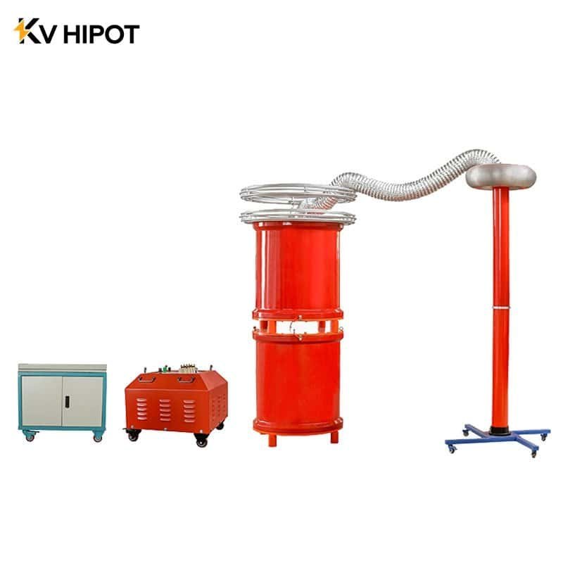
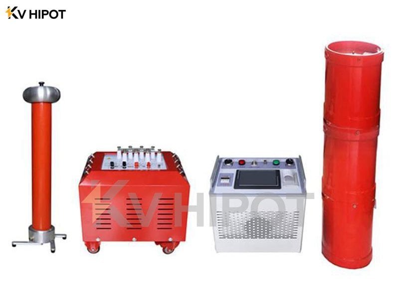
| Suitable Test Equipment | High-Voltage AC Hipot Tester with moderate kVA rating | AC Resonant Test System with high kVA rating to handle the high charging current |
What measurement accuracy and resolution are non-negotiable for reliable transformer diagnostics at high voltages?
Minor reading errors from your test equipment seem insignificant. But in diagnostics, these small errors can hide serious developing faults, making your predictive maintenance program useless and putting valuable assets at risk. For reliable transformer diagnostics, an accuracy of at least 0.5% for Tan Delta/Power Factor and 0.1% for turns ratio is non-negotiable.
High resolution is crucial for detecting the small, incremental changes year-over-year that signal insulation degradation or winding movement. Accuracy tells you how close a measurement is to the true value, while resolution tells you the smallest change the instrument can detect.
Think of it like a bathroom scale. An accurate scale tells you your true weight. A high-resolution scale can tell if you’ve gained a single gram. For diagnostic testing, you need both. You need an accurate reading to compare against industry standards, and you need high resolution to see tiny changes from the test you did last year. Spotting a 0.01% change in Tan Delta could be the first warning of moisture ingress in a multi-million dollar transformer. An instrument with poor resolution would miss this completely, giving you a false sense of security.
| Diagnostic Test | Why Accuracy is Critical | Why Resolution is Critical |
|---|---|---|
| Tan Delta / Power Factor | An inaccurate reading can misclassify insulation as “Good” when it is actually “Marginal,” delaying necessary maintenance. | Required to detect very small increases in dielectric losses year-on-year, which is a key indicator of aging or contamination. |
| Sweep Frequency Response Analysis (SFRA) | Ensures the frequency response “fingerprint” is true to the transformer’s actual mechanical condition for comparison with baseline data. | Allows the detection of very subtle shifts in resonant frequencies, which can indicate minor but significant winding deformation. |
| Transformer Turns Ratio | Verifies the transformer is meeting its nameplate specification. An error of 0.5% can indicate a serious problem like shorted turns. | Can help identify a single shorted turn in a high-turn-count winding, which might only cause a very small deviation in the ratio. |
Why does the capacitance range of an AC Resonance Test System matter for testing long transmission cables?
You have a powerful AC resonant system that works perfectly on shorter cables. But when you connect it to a new, long transmission line, it keeps tripping or fails to build voltage, causing major project delays. The capacitance range of an AC Resonance Test System is its operational sweet spot. The system uses internal variable reactors to create an LC resonant circuit with the cable.
If the cable’s capacitance falls outside this tunable range, the system cannot achieve resonance and cannot build up test voltage. An AC resonant system works by matching its internal inductance (XL) to the cable’s capacitive reactance (XC). When XL equals XC, the circuit resonates, allowing the system to build up a very high test voltage using a much smaller power source.
This is a huge advantage. However, the system’s reactor can only provide a specific range of inductance. This directly translates into a specific range of capacitance it can resonate with. If your cable is too short (too little capacitance) or too long (too much capacitance), the test set’s reactor cannot adjust enough to match it. The system will fail to resonate, and the test cannot be performed. This is why you must calculate the expected capacitance of your cable and choose a resonant system whose range covers that value.
| Cable Length | Approximate Capacitance (example) | Status for a test set with 0.5µF – 2.0µF range |
|---|---|---|
| 1 km | 0.2 µF | Too Low. Capacitance is outside the tester’s minimum range. Test will fail. |
| 5 km | 1.0 µF | Ideal. Capacitance is well within the tester’s operational range. |
| 10 km | 2.0 µF | At Limit. Capacitance is at the maximum limit. May work but with no margin. |
| 12 km | 2.4 µF | Too High. Capacitance is outside the tester’s maximum range. Test will fail. |
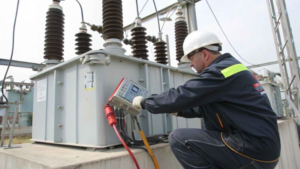
How do environmental specifications (temperature, humidity, altitude) affect the performance of on-site testing equipment?
Your test equipment works perfectly in the controlled environment of your lab. But when you take it on-site to a location that is hot, humid, or at a high altitude, the readings become unstable and unreliable. Environmental factors directly impact test results and equipment safety. High humidity can provide a conductive path on insulator surfaces, skewing insulation resistance readings. High temperatures can cause electronic components to drift. High altitude reduces air’s insulating ability, increasing the risk of external flashover.
Every piece of high-voltage test equipment is designed to operate within a specific environmental envelope. When you operate outside of it, you get problems. High humidity can make a perfectly good insulator look bad by allowing leakage current to flow over its surface. High ambient temperatures can heat up the internal electronics, causing their values to change and leading to inaccurate measurements. The most dangerous factor is altitude. Air is a primary insulator. At high altitudes, the air is thinner and provides less insulation. This means the safe clearance distance between high-voltage parts and ground is reduced, increasing the risk of a dangerous and damaging flashover from your test set itself. Always check the site conditions against your equipment’s datasheet before starting a job.
| Environmental Factor | Impact on Measurement Accuracy | Impact on Equipment Safety & Operation |
|---|---|---|
| High Temperature | Can cause drift in sensitive measurement circuits, affecting the accuracy of low-level signals like Tan Delta. Can also affect the asset’s properties, requiring temperature correction. | May cause the equipment to overheat and shut down. Can accelerate the aging of internal electronic components. |
| High Humidity | Can dramatically lower insulation resistance readings due to surface condensation, leading to false failures. May affect Tan Delta measurements if bushings are not perfectly clean. | Increases the risk of condensation forming inside the equipment, which can lead to internal short circuits. |
| High Altitude | Less direct impact on most measurements, but requires correction factors for some tests like oil breakdown voltage (BDV). | Significantly reduces the dielectric strength of air. Increases the risk of external flashover on test leads and terminals, requiring larger safety clearances. |
To choose the right HV test gear, look beyond the voltage. Analyze the load capacity, measurement accuracy, and environmental specs to ensure reliable, safe, and meaningful results on your 110kV+ assets.