What is current injection testing?
Your electrical system has circuit breakers to prevent disaster, but how can you be sure they will actually work when a fault happens? This uncertainty creates a major risk for your equipment and personnel. Current injection testing is a diagnostic method used to verify the performance of protective devices like circuit breakers and relays.
A specialized test set injects a controlled electrical current to simulate an overcurrent or fault condition, ensuring the device trips correctly. This testing process is the only way to prove that the heart of your electrical safety system is functioning as designed. It moves you from assuming protection to knowing you have it. Let’s explore the details of this critical maintenance procedure.
What is the primary current injection test?
You need to test the entire protection system, not just one part. Testing only the relay leaves the current transformer and wiring untested, which means a failure in those parts will still cause a catastrophe. A primary current injection test involves injecting a high current, often hundreds or thousands of amperes, directly through the main conductors of a circuit breaker.
This comprehensive test validates the entire protection chain: the current transformer (CT), all wiring, and the trip unit itself. This test is the most realistic simulation of a real-world overcurrent event. At my factory, we design primary injection testers to be powerful enough to handle large industrial breakers but also precise enough to give you trustworthy results. The goal is to make sure that when a real fault occurs, every single component in the trip circuit works together perfectly to clear the fault and protect your assets. This end-to-end verification is crucial during the commissioning of new equipment and for critical periodic maintenance, as it leaves no part of the system unchecked.
Components Verified by Primary Injection
| Component | Function | Why Testing It Matters |
|---|---|---|
| Current Transformer (CT) | Steps down high primary current to a low level for the trip unit. | Verifies the CT is not saturated, shorted, or open and has the correct ratio. |
| Wiring and Terminations | Carries the signal from the CT to the trip unit. | Checks for loose connections, corrosion, or breaks that would interrupt the signal. |
| Trip Unit / Relay | The “brain” that detects the fault and signals the breaker to open. | Confirms the trip unit’s settings are correct and its internal logic is working. |
| Breaker Mechanism | The mechanical parts that physically open the circuit. | Ensures the breaker is not stuck and can open within the specified time. |
What is the purpose of an injection test?
You have installed expensive circuit breakers to protect your valuable assets. But are they just sitting there, or will they actually work? Assuming they will work without proof is a huge gamble. The purpose of a current injection test is to prove that a circuit breaker or protective relay will operate as specified under fault conditions. This verification ensures system safety, prevents equipment damage, and confirms the correct coordination between protective devices.
By performing these tests, you are essentially asking the breaker a question: “Will you trip at the exact current and time that you are supposed to?” The answer to this question is vital. A breaker that trips too late can allow catastrophic damage to a motor or transformer. A breaker that trips too soon can cause nuisance outages, shutting down a critical process for no reason. Our job as a manufacturer is to provide you with the tools to get this answer reliably. The ultimate goal is to maintain a safe and stable power system, and regular injection testing is a cornerstone of that maintenance philosophy.
Key Objectives of Current Injection Testing
| Objective | Description | Direct Benefit |
|---|---|---|
| Verify Protection Settings | Confirms the breaker trips at the current levels and times set by the engineers. | Prevents equipment damage from overloads and short circuits. |
| Ensure System Coordination | Makes sure the breaker closest to the fault trips first, isolating the problem. | Avoids widespread power outages by localizing the fault. |
| Commissioning New Gear | Guarantees that newly installed equipment is working correctly before it goes live. | Catches manufacturing defects or shipping damage before they cause issues. |
| Preventative Maintenance | Identifies degradation or problems in aging breakers before they fail. | Increases system reliability and reduces the risk of unplanned downtime. |
What is the current injection method?
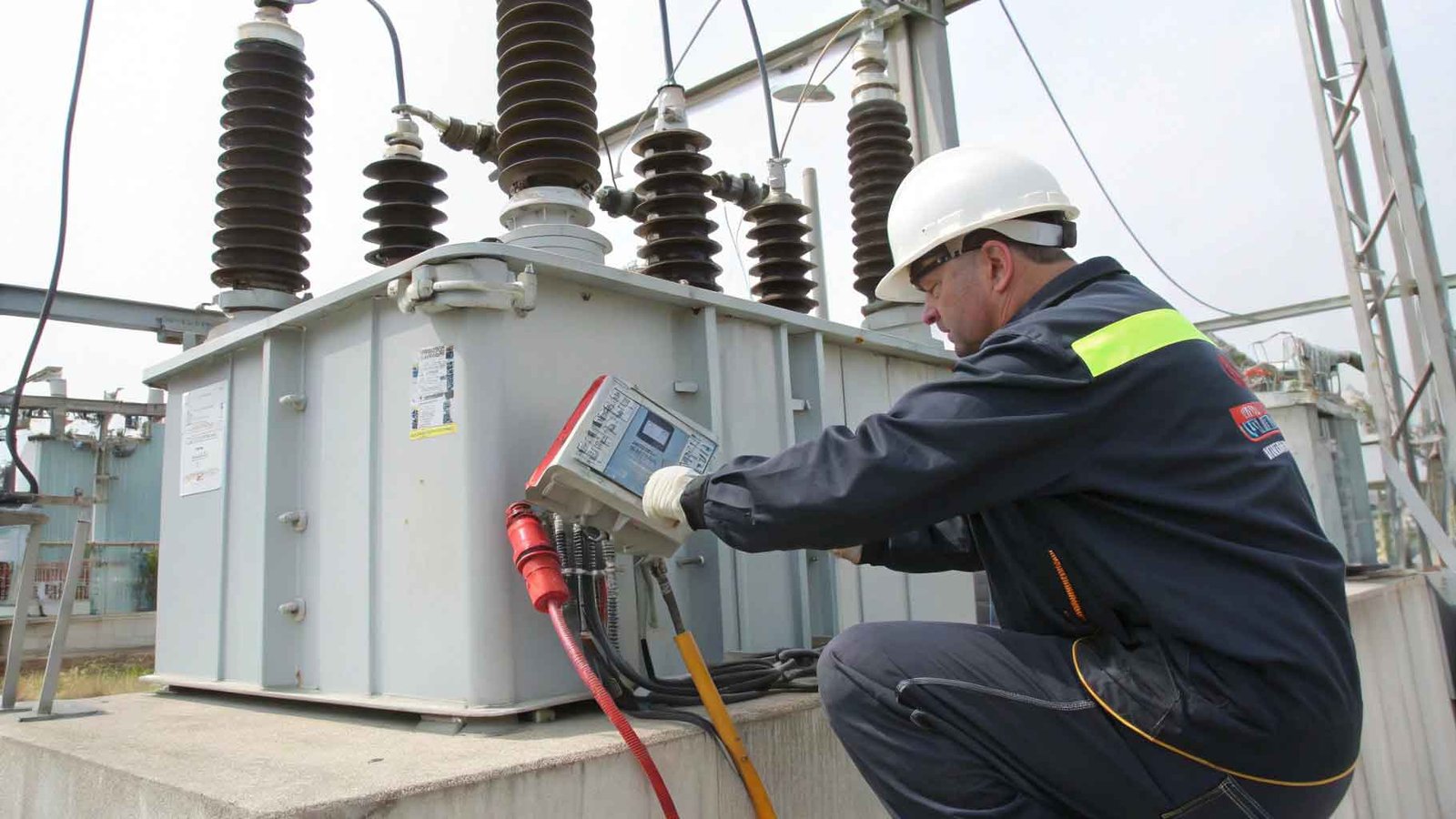
You know you need to inject current, but what is the actual process? Doing it wrong can damage the equipment you are trying to test or create a serious safety hazard for the technician. The current injection method is a systematic process. It involves safely isolating the device, connecting a specialized test set, programming the test parameters (current and time), and then applying the controlled current to measure the device’s reaction time and trip level. At its core, the method is about safely creating an unsafe condition in a controlled way.
First, the breaker must be completely de-energized and isolated from the electrical system. Then, the high-current cables from our test set are connected across the breaker’s primary terminals. The technician then uses the tester’s controls to set the output current to a specific multiple of the breaker’s rating—for instance, 300% to test its overload protection. When the test is initiated, the set injects the current and a timer starts. The timer stops the instant the breaker trips open, giving a precise measurement of its performance that can be compared against the manufacturer’s specifications.
The Standard Current Injection Procedure
| Step | Action | Safety Consideration |
|---|---|---|
| 1. Isolate & Lockout | De-energize and lock out the circuit breaker according to safety protocols. | This is the most critical step to prevent electric shock. Always verify zero energy. |
| 2. Connect Test Set | Attach the high-current output leads of the injection tester to the breaker. | Ensure connections are tight and secure to prevent arcing during the high-current test. |
| 3. Set Parameters | Program the desired test current and maximum test duration on the tester. | Refer to the breaker’s time-current curve (TCC) to set the correct test values. |
| 4. Apply Current | Clear the area and initiate the test from the tester’s control panel. | Stand clear of the breaker during the test as it will operate mechanically. |
| 5. Record Results | Document the trip time and current level. Compare results to specifications. | Accurate records are essential for maintenance tracking and compliance reporting. |
How is current injection used to test a circuit breaker’s trip unit?
The trip unit is the “brain” of the breaker. But how do you test if its logic and settings are correct? A misconfigured trip unit can cause nuisance tripping or fail to trip during a real fault. Current injection directly tests a trip unit by creating the exact overcurrent conditions it is designed to detect.
By injecting specific currents, you can verify its long-time, short-time, instantaneous, and ground fault trip functions against its time-current curve (TCC). A modern electronic trip unit has several adjustable settings that define how it responds to different types of overcurrents. A “long-time” setting protects against simple overloads, while an “instantaneous” setting responds immediately to a massive short circuit.
When we perform a test, we are checking each of these functions one by one. For example, to test the long-time function, we might inject 3 times the breaker’s rated current and check that it trips within the specified time window, perhaps 10 to 30 seconds. To test the instantaneous function, we would inject a much higher current, maybe 10 times the rating, and expect the breaker to trip in milliseconds. This process confirms the “brain” is working exactly as it should.
Testing Trip Unit Protection Functions
| Protection Function | Protects Against | Typical Test Current (x Rating) | Expected Trip Time |
|---|---|---|---|
| Long Time (LT) | Sustained overloads (e.g., a struggling motor). | 2x – 3x | Seconds to minutes |
| Short Time (ST) | Low-level short circuits or faults. | 5x – 8x | Milliseconds to seconds |
| Instantaneous (INST) | High-level, dangerous short circuits. | 10x – 15x | Less than 50 milliseconds |
| Ground Fault (GF) | Current leaking to ground. | A specific percentage of the rating. | Milliseconds to seconds |
What is the difference between primary and secondary injection testing?
You hear both terms used in the industry. Are they the same thing, and when should you use one over the other? Choosing the wrong test could give you a false sense of security by not testing all critical parts. Primary injection testing is the most complete test. It passes high current through the entire breaker circuit, testing the CTs, wiring, and trip unit together. Secondary injection testing is simpler; it injects a low-current signal directly into the trip unit, bypassing the CTs and primary wiring. Think of it this way: a primary injection test is like a full dress rehearsal for a real fault. It makes sure every actor in the play knows their part.
A secondary injection test is like testing just one actor’s lines in their dressing room. It’s useful for quickly checking the logic of the trip unit, especially during troubleshooting, because it’s faster and requires less equipment. However, it cannot tell you if the CT is faulty or if there is a loose wire. A comprehensive maintenance program often uses both methods. Secondary injection can be done more frequently for a quick check-up, while the more intensive primary injection is performed during major shutdowns or commissioning to guarantee the entire system’s integrity. For critical infrastructure, there is no substitute for a full primary injection test.
Primary vs. Secondary Injection Testing: A Direct Comparison
| Feature | Primary Injection Testing | Secondary Injection Testing |
|---|---|---|
| Scope | Tests CTs, wiring, and trip unit (the entire system). | Tests only the trip unit or relay logic. |
| Current Level | High current (100s to 1000s of Amps). | Low current/voltage signal (milliamps to a few amps). |
| Complexity | More complex, requires breaker isolation and heavy cables. | Simpler, connects directly to the trip unit test port. |
| Time Required | Slower; requires more setup time. | Faster; can be done in a fraction of the time. |
| Best Application | Commissioning, major maintenance, and post-repair verification. | Routine checks, troubleshooting the trip unit, calibration. |