Transformers are essential in power systems due to their ability to regulate voltage, ensuring efficient transmission over long distances while minimizing energy loss. They provide crucial isolation, protecting sensitive electrical equipment from surges and faults. Additionally, transformers facilitate effective load management, balancing electricity distribution across different phases.
As renewable energy sources become more prevalent, transformers play a key role in adapting their variable outputs to the grid’s requirements. Overall, these devices enhance the reliability, flexibility, and stability of electrical infrastructure, making them indispensable in modern power systems.

Insulation aging can occur due to thermal stress, electrical stress, and environmental factors like humidity and contamination. Over time, elevated temperatures can accelerate chemical breakdown in materials, leading to decreased dielectric strength. Additionally, moisture ingress and exposure to contaminants can compromise insulation integrity, resulting in potential failures.
Insulation testing is crucial for preventive maintenance, helping to identify insulation deterioration before failures occur. Techniques such as insulation resistance testing and dielectric response analysis allow for early detection of issues, enabling timely repairs or replacements. Regular testing ensures the reliability and longevity of transformers, ultimately enhancing system safety and performance.
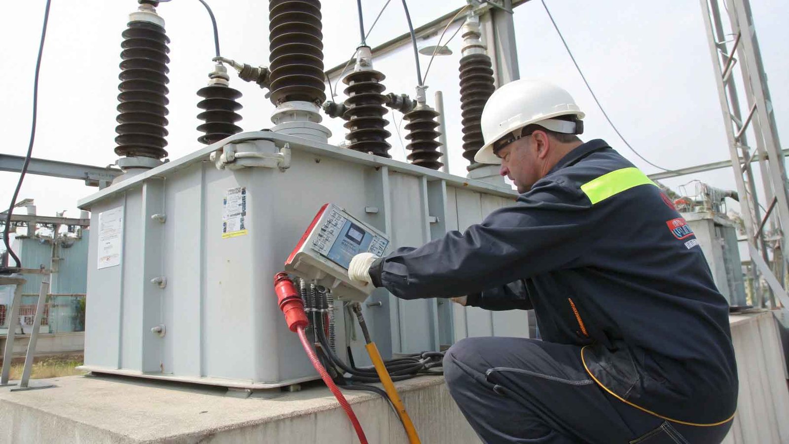
Transformer resistance testing is an important method for assessing the performance of a transformer’s internal windings and insulation system. It primarily involves measuring the insulation resistance and winding resistance to determine the health of the equipment. Here are the key aspects of transformer resistance testing:
Insulation Resistance Testing
Purpose: To measure the insulation resistance between the transformer windings and ground, assessing the condition of the insulation materials.
Principle: insulation resistance testing is based on measuring the resistance value of insulation materials when a voltage is applied. This test typically uses an insulation resistance tester, which applies a high voltage (usually 500V or 1000V) to the insulation material and measures the small current that flows through it. According to Ohm’s law (V = IR), the insulation resistance value can be calculated. A higher insulation resistance indicates good performance of the insulation material, while a lower resistance may suggest aging, moisture, or other defects, signaling the need for further inspection or maintenance
Method: A megohmmeter is used, typically applying high voltage (such as 2500V or 5000V) to measure the resistance value between the windings and ground.
Standards: The insulation resistance value should exceed a certain threshold (e.g., usually above 1MΩ or higher) to ensure the effectiveness of the insulation system.
Winding Resistance Testing
Purpose: To measure the resistance of the transformer windings, determining the integrity of the connections and current paths.
Method: A low-voltage DC power source and measurement instruments (like a resistance tester) are used to measure the winding resistance.
Application: This test can check the balance between windings and assess the overall health of the transformer.
Absorption Ratio and Polarization Index
Absorption Ratio: This measures the change in insulation resistance over different time intervals (e.g., 1 minute and 10 minutes) to assess the moisture absorption capability of the insulation materials.
Polarization Index: By comparing the insulation resistance values at different times (like 1 minute and 10 minutes), this index evaluates the insulation performance, typically aiming for a value above 1.3.
Standard Requirements for Transformer Insulation Resistance and Absorption Ratio, Polarization Index Test Results
Handover Test Standards:
The insulation resistance value should not be less than 70% of the product’s factory test value.
If the measured temperature differs from the temperature at which the product was factory tested, values can be adjusted to the same temperature for comparison.
For transformers with a voltage rating of 35kV and above, and a capacity of 4000kVA or more, the absorption ratio should be measured. The absorption ratio should show no significant difference when compared to the factory value; it should not be less than 1.3 at room temperature. If R60s is greater than 3000MΩ, the absorption ratio assessment may be waived.
Judgment Criteria:
For transformers with a voltage rating of 220kV and above and a capacity of 120MVA or more, it is appropriate to use a 5000V megger meter to measure the polarization index. The measured value should not show significant difference compared to the factory value. At room temperature, it should not be less than 1.3. If R60s exceeds 10000MΩ, the polarization index assessment may be waived.
Preventive Test Standards for Insulation Resistance Testers:
Insulation resistance should be adjusted to the same temperature; compared with previous test results, it should show no significant changes, generally not less than 70% of the last value.
For transformers rated 35kV and above, the absorption ratio should be measured; it should be no less than 1.3 at room temperature. If the polarization index is low, the absorption ratio should not be less than 1.5.
When insulation resistance exceeds 10000MΩ, the absorption ratio should not be less than 1.1, or the polarization index should not be less than 1.3.
Key Points:
Use a 2500V or 5000V high voltage insulation tester for transformers rated 220kV and above, with a minimum output current of 3mA.
Ensure that the test winding is fully discharged before measurement.
The measurement temperature should be based on the top oil temperature, and all measurements should be taken as closely as possible in temperature.
Attempt to measure at an oil temperature below 50℃; insulation resistance values at different temperatures should be adjusted accordingly.
The absorption ratio and polarization index should not be adjusted for temperature.
For closed cable outlets or GIS transformer cable outlets, measurements can be taken at the neutral point, while other independent windings should be short-circuited to ground.
If necessary (e.g., in cases of oil dielectric loss, excessive moisture, or leakage), insulation tests should be conducted on the core.
Additional Points:
Measure the insulation resistance between the iron core and ground, the iron core and clamps, and clamps and ground.
Use a 2500V electronic megohmmeter for measurements, recording the insulation resistance value after one minute, ensuring no flashover or breakdown occurs.
Handover tests should use a 2500V megohmmeter (for pre-testing on old operational transformers, a 1000V megohmmeter can be used).
Only measure the core and clamps with an external grounding conductor.
If required (e.g., for oil chromatography tests), measure the insulation resistance of the capacitive casing end screen to ground using a 2500V megohmmeter. The insulation resistance at the flange of the “pumping casing” should not be less than 1000MΩ, accounting for any dirt or moisture interference.