

Choosing a test voltage from the words “33 kV cable” alone can overstress the circuit, under-test it, or produce a report the asset owner cannot accept.
There is no universal test voltage for every 33 kV cable. If the nameplate is 19/33 (36) kV and the approved procedure specifies 3U₀ sinusoidal VLF, the calculated level is 57 kV RMS, or approximately 81 kV peak. An 18/30 (36) kV cable would produce a different result.
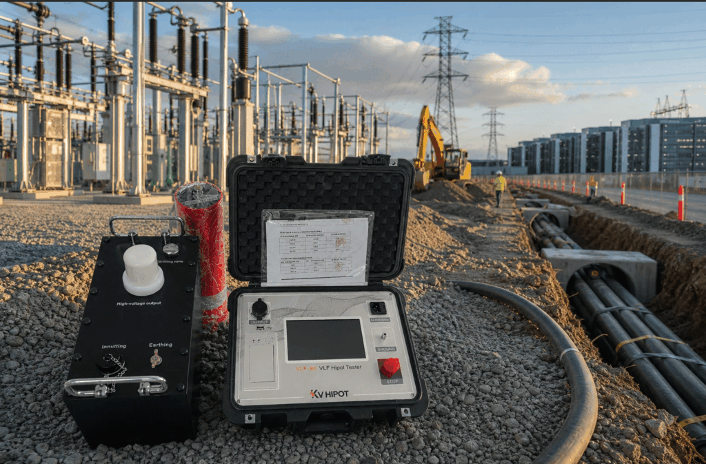
The calculation is simple; deciding whether the calculation applies is the important part. This guide explains how to identify U₀, select the governing test procedure, distinguish RMS from peak voltage, check the tester against cable capacitance, and interpret the result without claiming more than a withstand test can prove.
Is 57 kV RMS the Correct VLF Test Voltage for Every 33 kV Cable?
No. The often-quoted 57 kV value is the result of multiplying a 19 kV phase-to-ground rating by three. It is valid only when the cable rating and approved test procedure support that calculation.
The label “33 kV” is incomplete because it may refer to the system’s nominal phase-to-phase voltage rather than the cable’s full rated-voltage designation. Two projects connected to nominally similar networks may use different cable markings or different owner requirements.
For a sinusoidal waveform, the arithmetic examples are:
| Example cable marking | U₀ used in the calculation | Example multiplier | Calculated RMS voltage | Sinusoidal peak equivalent |
|---|---|---|---|---|
| 18/30 (36) kV | 18 kV | 3U₀ | 54 kV RMS | Approximately 76.4 kV peak |
| 19/33 (36) kV | 19 kV | 3U₀ | 57 kV RMS | Approximately 80.6 kV peak |
These are mathematical examples, not universal test prescriptions. The multiplier and duration must come from the current standard, project specification, cable manufacturer, and approved test plan. Do not substitute a calculated value for a standard table that applies to a specific waveform or test category.
Before entering a voltage into the test set, record:
- The complete cable marking, including U₀/U (Uₘ)
- Insulation type and cable manufacturer
- Cable length and estimated or measured capacitance
- Number and type of joints and terminations
- Installation, acceptance, or maintenance objective
- VLF waveform and frequency
- Applicable standard edition and project specification
- Required test duration and acceptance authority
If any of these inputs are unknown, the responsible engineer should resolve them before the test. Increasing voltage “to be safe” is not a safe substitute for missing cable data.
What Do U₀, U, and Uₘ Mean on a 33 kV Cable Nameplate?
U₀, U, and Uₘ describe different voltage relationships. Confusing them is one of the most common reasons for an incorrect VLF setting.
- U₀ is the cable’s rated power-frequency voltage between one conductor and earth or the metallic screen.
- U is the rated voltage between conductors.
- Uₘ is the highest system voltage for which the cable and its accessories are designed.
For a 19/33 (36) kV cable, U₀ is 19 kV, U is 33 kV, and Uₘ is 36 kV. If an approved procedure requires a test level expressed as a multiple of U₀, the calculation starts from 19 kV—not from 33 kV.
The familiar calculation 33 kV ÷ √3 ≈ 19.05 kV can help explain the phase-to-ground relationship in a three-phase system. It should not replace the nameplate or cable datasheet, however. Cable voltage designations and earthing conditions vary across markets, and a nominal 33 kV network does not automatically prove that every installed cable is marked 19/33 (36) kV.
Use this order of evidence:
- Read the cable sheath marking or manufacturer’s datasheet.
- Confirm the network and grounding arrangement.
- Check the project cable schedule and accessory ratings.
- Identify the approved field-test procedure.
- Resolve any difference before calculating the test voltage.
Which Standard and Test Purpose Determine the Voltage and Duration?
The cable class does not determine the test plan by itself. The governing document must also match the cable construction, test method, waveform, lifecycle stage, and decision the test is intended to support.
IEEE 400.2-2024 covers field withstand and diagnostic testing of shielded power cable systems using VLF energization below 1 Hz. It supersedes the 2013 edition. IEEE 400-2023 is the broader guide for evaluating available field-test methods for shielded cable systems rated 5 kV and above.
IEC 60502-2:2014+A1:2024 covers construction, dimensions, and test requirements for specified extruded-insulation power cables with Uₘ up to 36 kV. A project may also impose utility, national, contractual, cable-manufacturer, or accessory-manufacturer requirements.
The test purpose changes the engineering question:
| Test purpose | Typical question | Evidence available before testing | Why the plan may differ |
|---|---|---|---|
| Installation check | Was the cable damaged during transport or installation? | New-cable data, installation records, cable ends may still be accessible | Accessories and final circuit configuration may not yet be complete |
| Acceptance test | Is the completed cable system acceptable before energization? | Cable, joints, terminations, installation and commissioning records | The complete circuit and workmanship are under review |
| Maintenance test | Can a service-aged circuit remain in operation under the owner’s program? | Service history, previous tests, failures, load and outage consequences | Age, uncertainty, and failure consequence require an asset-specific decision |
Terminology can vary between standards and owners, so the method statement should define what “installation,” “acceptance,” and “maintenance” mean for that project.
Do not combine a voltage from one edition, a duration from another document, and a waveform from the equipment brochure. Record the exact source for each test parameter. Our VLF cable testing standards guide explains how to review standards, waveform, calibration, and compliance documents as one evidence set.
How Do You Convert U₀ into VLF RMS and Peak Voltage?
For a sinusoidal VLF output, RMS and peak values are related by the same mathematical relationship used for other sine waves:
Vpeak = Vrms × √2
Vrms  = Vpeak ÷ √2
If the approved test level is 3U₀ and U₀ is 19 kV:
3 × 19 kV = 57 kV RMS
57 kV × 1.414 = 80.6 kV peak
If U₀ is 18 kV:
3 × 18 kV = 54 kV RMS
54 kV × 1.414 = 76.4 kV peak
The conversion is valid only for a sine wave. Do not automatically apply √2 to a cosine-rectangular, rectangular, or other VLF waveform. The procedure and instrument documentation must define how the applicable test voltage is expressed and what the display reports.
Before testing, answer four questions:
- Does the project specify sinusoidal or another VLF waveform?
- Is the required voltage stated in RMS, peak, or another defined basis?
- Does the tester display RMS, peak, or both?
- Does the calibration certificate cover the voltage range and measurement basis being used?
A tester marked “80 kV” cannot be approved from the model name alone. An example requirement of approximately 80.6 kV peak already exceeds 80 kV mathematically, before considering whether the published rating is peak or RMS and whether the unit can maintain that voltage at the cable’s capacitance. Confirm the manufacturer’s definition and configuration-specific load chart instead of rounding the requirement to fit the equipment.
See which VLF tester specifications matter for a more detailed explanation of RMS, peak voltage, waveform, frequency, and load capacity.
Do Sinusoidal and Cosine-Rectangular VLF Waveforms Use the Same Test Values?
Not necessarily. Both are VLF waveforms, but their voltage definitions, stress distribution, test levels, and diagnostic compatibility must be taken from the applicable procedure.
A sinusoidal VLF source produces a low-frequency sine wave. This waveform supports the familiar RMS-to-peak conversion and is commonly used as an energization source for compatible tan delta or partial-discharge systems.
A cosine-rectangular source changes polarity through shaped transitions and holds voltage differently during parts of the cycle. It should not be treated as a sine wave with a different-looking trace. Transferring a voltage value from one waveform table to another can apply a different electrical stress than the procedure intended.
Waveform and measurement method must match the test objective; withstand, tan delta, and partial-discharge testing do not answer the same question.
The test report should therefore state:
- Waveform type
- Nominal and actual frequency
- Voltage basis displayed by the instrument
- Target and achieved voltage
- Ramp and hold sequence
- Test duration
- Cable capacitance or load estimate
- Applicable procedure and edition
The phrase “IEEE-compliant waveform” is not enough. Compliance requires the equipment configuration, test settings, calibration evidence, cable system, and field procedure to match the relevant requirements.
Should a 33 kV XLPE Cable Be Tested with VLF, DC, or Resonant AC?
For an installed XLPE or EPR cable system, VLF withstand is a commonly specified field method, but the correct choice still depends on the approved program. High-voltage DC should not be presented as the default alternative for extruded-insulation AC cable merely because a DC test set is available.
The methods answer different questions and impose different stresses:
| Method | Appropriate use to investigate | Main limitation |
|---|---|---|
| VLF withstand | Whether a shielded cable system survives the specified low-frequency AC voltage and time | Pass/fail evidence does not identify every defect or predict remaining life |
| VLF tan delta | Bulk insulation loss, phase comparison, and condition trends under an applicable diagnostic procedure | Interpretation requires baselines, voltage steps, cable type, and comparative data |
| VLF partial discharge | PD activity and, with a suitable system, possible defect location | Setup, noise control, accessories, calibration, and expert interpretation are critical |
| Resonant or other continuous AC | Approved withstand or diagnostic work where a continuous AC source is required | Equipment size and field logistics can be greater, especially for high-capacitance circuits |
| High-voltage DC | Laminated-dielectric AC cable systems when covered by the applicable procedure, or other specifically authorized tasks | It is not a universal substitute for VLF testing of XLPE/EPR cable systems |
IEEE 400.1-2018 addresses high-voltage DC field testing of laminated-dielectric shielded AC cable systems. IEEE 400.3-2022 covers field partial-discharge diagnostic testing of shielded power cable systems.
Avoid three misleading claims:
- VLF withstand does not directly prove that a cable has no water trees.
- A VLF pass does not prove that joints and terminations are defect-free.
- A DC test is not automatically harmful or obsolete for every cable; its suitability depends on cable construction and the governing procedure.
The useful decision is not “Which method is best?” It is “Which method produces the evidence required for this cable system and this maintenance or commissioning decision?”
Can the VLF Tester Supply the Required Voltage at the Cable’s Capacitance?
Maximum voltage and maximum capacitance are not independent ratings. A VLF source that reaches its nameplate voltage on a small test load may be unable to maintain that voltage on a long cable at 0.1 Hz.
For a sinusoidal capacitive load, charging current can be estimated as:
I = 2πfCV
Where:
Iis RMS charging currentfis frequency in hertzCis total circuit capacitance in faradsVis RMS test voltage
For example, a 1.0 µF circuit at 57 kV RMS and 0.1 Hz requires approximately:
I = 2 × π × 0.1 × 1.0 × 10⁻⁶ × 57,000
I ≈ 0.0358 A, or 35.8 mA RMS
At the same voltage and capacitance, the ideal sinusoidal charging current is proportional to frequency. A 50 Hz source would require about 500 times the charging current of a 0.1 Hz source; a 60 Hz source would require about 600 times as much. This is why VLF equipment can be much more portable than conventional power-frequency equipment for long MV cables.
The calculation does not prove that a particular tester can run the test. Request a load chart showing the permitted combination of:
- Output voltage
- Frequenza
- Cable capacitance
- Waveform
- Test duration or duty cycle
- Ambient and input-supply limits
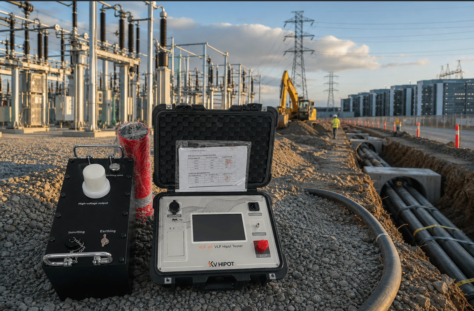
KV HIPOT publishes VLF configurations with maximum-output-voltage labels of 30, 50, 60, and 80 kV and selectable frequencies including 0.1, 0.05, and 0.02 Hz. These ratings are configuration-dependent. For example, the published 60 kV configuration lists different load capability at each frequency; those figures must not be transferred to another voltage configuration.
Review the exact KV HIPOT VLF tester configuration and obtain a written voltage-frequency-load confirmation for the longest planned circuit. If the cable exceeds the 0.1 Hz capability, do not simply reduce frequency: first confirm that the governing procedure permits the lower frequency and defines any corresponding change in duration or interpretation.
How Should a 33 kV Cable Circuit Be Prepared and Tested Safely?
The numerical voltage is only one part of a valid test. Incorrect circuit identification, isolation, grounding, or post-test discharge can create a greater risk than a calculation error.
A controlled test begins with verified isolation and ends with discharge and visible grounding—not when the timer stops.
A site procedure should include at least the following hold points:
- Confirm authorization and scope. Identify the circuit, test objective, procedure, responsible engineer, switching authority, and stop criteria.
- Identify every cable end and connected device. Review the single-line diagram, cable schedule, phasing, joints, terminations, transformers, arresters, instrument transformers, electronics, and parallel circuits.
- Isolate the test circuit. Apply the owner’s switching and lockout/tagout rules. Disconnect or protect equipment that is not included in the approved test circuit.
- Prove de-energized, discharge, and ground. Treat every conductor as energized until it has been tested dead and grounded under the site procedure.
- Inspect the test set and leads. Confirm model, calibration status, voltage basis, accessories, lead condition, clearances, earth connections, emergency stop, and interlocks.
- Establish the test zone. Use barriers, warning signs, communications, and a single person responsible for energization. Keep cable ends under control at all locations.
- Make and independently verify connections. Connect the high-voltage lead and ground the metallic screen, non-tested phases, and associated conductors as required by the approved method.
- Enter the approved settings. Verify waveform, frequency, target voltage, ramp, duration, trip limits, cable capacitance, and report identifiers before removing the temporary test ground from the energized conductor.
- Energize and monitor. Raise voltage only under authorization. Stop for unexpected current, unstable voltage, flashover, unusual noise, smoke, loss of communication, weather change, or an instrument protection event.
- Discharge and visibly ground. Allow the test set to complete its discharge sequence, confirm voltage absence using the approved method, apply a visible ground, and maintain it for the required time before touching or reconnecting the circuit.
Our safe VLF cable test procedure provides a fuller planning and reporting checklist. It must still be adapted to the local rules and equipment manual.
What Does a VLF Withstand Pass or Failure Actually Tell You?
A valid VLF withstand pass means the tested cable system survived the specified waveform, voltage, and duration under the recorded conditions. It does not certify that the insulation is free from every defect, guarantee future service life, or replace all diagnostic testing.
Interpret the outcome within clear boundaries:
| Outcome | What it supports | What it does not prove | Appropriate next step |
|---|---|---|---|
| Valid pass | The circuit withstood the approved test condition | No defects, no PD, or guaranteed remaining life | Complete discharge, document the result, and follow the owner’s return-to-service process |
| Breakdown or trip confirmed as cable-system failure | The circuit did not withstand the test condition | Exact fault component or root cause | Ground the circuit, preserve records, locate and repair the fault, then obtain approval for retesting |
| Instrument trip or unstable run | The planned test was not completed | Cable failure | Check load capability, connections, input supply, settings, environment, and instrument records before deciding what happened |
| Procedure deviation | Evidence may not be acceptable | Pass or fail under the intended procedure | Record the deviation and obtain engineering disposition; do not quietly adjust the report |
For an aged cable, withstand evidence may be supplemented by diagnostics when the maintenance decision requires more than a pass/fail result:
- Use tan delta when the question concerns broad insulation condition, phase comparison, or trend.
- Use partial-discharge testing when the question concerns active localized discharge and possible location.
- Use an oversheath test when the question concerns the protective outer sheath rather than the primary insulation.
- Review service history, previous measurements, fault records, joints, and terminations before making a remaining-life decision.
The final report should identify the cable, tested phase, accessories included, test set and serial number, calibration reference, waveform, frequency, voltage basis, target and achieved voltage, duration, capacitance, environmental conditions, interruptions, observations, discharge, grounding, and authorized disposition.
What Should You Confirm Before Selecting a Tester or Approving the Test?
Use this checklist before requesting a quotation, approving a method statement, or traveling to site:
- Complete cable rating: U₀/U (Uₘ)
- Nominal system voltage and grounding arrangement
- Insulation type and cable manufacturer
- Cable length, conductor size, and capacitance
- Number and type of joints and terminations
- New installation, acceptance, or maintenance objective
- Applicable standard, edition, owner specification, and manufacturer instructions
- Required VLF waveform
- Required RMS, peak, or other voltage basis
- Approved test frequency, duration, ramp, and trip criteria
- Tester load capability at the required voltage and frequency
- Duty cycle and ambient operating limits
- Calibration scope and certificate validity
- Grounding, interlock, emergency stop, and discharge arrangement
- Equipment that must be disconnected or protected
- Required report fields and person authorized to accept the result
- Need for tan delta, PD, or oversheath testing
Sending this information to the equipment supplier is more reliable than asking, “Which VLF tester is suitable for a 33 kV cable?” See our guide on choosing the right VLF cable tester for a procurement-focused review.
Frequently Asked Questions
Is 57 kV RMS always the correct VLF voltage for a 33 kV cable?
No. It is the 3U₀ calculation for a cable with U₀ = 19 kV. A cable marked 18/30 (36) kV produces 54 kV RMS at 3U₀. Whether 3U₀ applies must come from the approved procedure.
Is an 80 kV VLF tester automatically suitable for this test?
No. Confirm whether 80 kV is a peak or RMS rating, the waveform, and the unit’s load capability at the required voltage, frequency, capacitance, and duration. A 57 kV RMS sine wave is approximately 80.6 kV peak.
Can I use a DC hipot tester on a 33 kV XLPE cable?
Do not select DC solely because the test set is available. For an XLPE cable system, use the test method authorized by the cable manufacturer, current standard, asset owner, and approved procedure. IEEE 400.1 addresses DC testing of laminated-dielectric AC cable systems, not a universal DC method for every XLPE circuit.
Does a VLF withstand test detect water trees or partial discharge?
A withstand test establishes whether the circuit survives the specified stress. It does not directly characterize every water tree or measure and locate PD. Use an applicable tan delta or PD procedure when the maintenance decision requires diagnostic information.
Can I reduce the frequency from 0.1 Hz to test a longer cable?
Lower frequency reduces charging current and may increase the testable capacitance, but the governing procedure must permit that frequency and define the corresponding test conditions. Never change frequency only to make an undersized tester complete the job.
Should all three phases be tested together?
Shielded MV cable phases are commonly tested individually, with the metallic screen and non-tested conductors grounded according to the approved connection diagram. Cable construction and connected equipment can change the arrangement, so follow the authorized procedure rather than a generic diagram.
Does a VLF pass mean the cable is safe for many more years?
No. It means the tested circuit survived the recorded test condition. Remaining-life decisions require service history, failure consequence, accessories, trend data, and any diagnostics specified by the asset owner.
How long should the 33 kV cable be tested?
Use the duration specified for the cable, waveform, lifecycle stage, and test objective in the current governing procedure. “15 to 60 minutes” is too broad to use as a universal setting without identifying the applicable row and conditions.

 English
  ไทย
ไทย  Tiếng Việt
  العربية
  Русский
  Italiano
  Español
  한국어
한국어  Português do Brasil
  Français
  Español de México
  Português
  Türkçe
  Čeština
  Español de Argentina
  Slovenčina
  Dansk
Dansk  Polski
  Deutsch
  Ελληνικά
  O‘zbekcha
  Bahasa Indonesia
  Română