With the ongoing development of the social economy and advancements in science and technology, electric energy has become an essential power source for both production and daily life. Various electric devices play a crucial role in the everyday lives of people. Wires and cables serve as the primary means of transporting electric energy to power equipment, occupying a vital position in the processes of power transmission and distribution.
As the main carrier in power systems, wires and cables must possess excellent electrical conductivity to enhance the economic efficiency of the system. Additionally, they must ensure reliable insulation properties to maintain the stability and safety of the power transmission network.
If the insulation performance is unstable or defective, it poses a serious risk to power safety, potentially leading to fires and other hazards. Therefore, to meet the operational demands of the power system, we must prioritize insulation performance and conduct insulation tests. Before use or upon finalizing a product design, standard testing methods must be employed to ensure that the insulation properties of wires and cables meet design and usage requirements.
Why Do We Need to Test the Insulation Resistance of Cables?
Testing the insulation resistance of cables is a critical component in power systems, primarily used to evaluate the integrity and performance of cable insulation. This testing helps identify potential insulation issues early, ensuring the safe and stable operation of the power system. Here’s a deeper analysis:
- Detection of Insulation Defects:
- Moisture Intrusion: During the installation or operation of cables, moisture can infiltrate the insulation layer due to external environmental factors (e.g., rain, groundwater). Moisture presence can significantly lower insulation resistance, increase leakage current, and even lead to short circuits. Insulation resistance testing can detect signs of moisture intrusion early, preventing further damage.
- Dirt and Pollution: Cables can be affected by pollutants such as dust and oil during operation. These contaminants can create conductive pathways on the insulation surface, compromising insulation performance. Insulation resistance testing can identify these pollutants, allowing maintenance personnel to clean or replace damaged cables promptly.
- Localized Defects: Cables may suffer mechanical damage during manufacturing, transportation, or installation, resulting in localized insulation defects. While these defects may not cause immediate failure, they can worsen over time, ultimately leading to cable failure. Insulation resistance testing can promptly identify these localized defects, enabling appropriate repair measures.
- Determining the Nature of Defects:
- If abnormalities are detected during a withstand voltage test, insulation resistance testing can further analyze the nature of these defects. For instance, partial discharge phenomena observed during the voltage test may indicate tiny cracks or air bubbles in the insulation layer. Insulation resistance testing can determine whether these defects significantly impact insulation performance, helping to decide if the cable needs immediate replacement or repair.
- Ensuring System Safety:
- Power cables are critical components in power transmission, and their insulation performance directly affects the safe and stable operation of the entire power system. Regular insulation resistance testing helps monitor the insulation condition of cables, preventing power outages due to insulation degradation. This is particularly important in high-voltage transmission systems, where insulation failures can lead to severe power accidents and jeopardize personal safety. Therefore, insulation resistance testing is essential for ensuring the reliability of power systems.
How to Test the Insulation Resistance of Cables
Here are the specific steps for testing cable insulation resistance are as follows:
1. Select a Suitable A Megger :
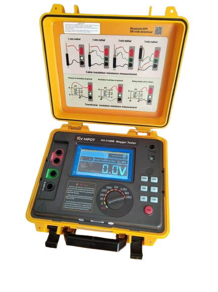
The insulation resistance value of a cable is influenced by the temperature at the time of measurement and the cable length. Detailed guidelines should be followed to select the appropriate megohmmeter (insulation resistance tester) for cables of different voltage ratings, along with the corresponding reference values for insulation resistance. This information will help you better understand the standards and requirements for cable insulation resistance testing.
1.1 Cable Voltage Rating and Megohmmeter Selection
| Cable Rated Voltage (kV) | Megohmmeter Voltage Rating (V) | Insulation Resistance Reference Value (20℃, MΩ) |
|---|---|---|
| 1 kV and below | 1000 V | ≥10 |
| 3 kV | 2500 V | ≥200 |
| 6 – 10 kV | 2500 V | ≥400 |
| 20 – 35 kV | 2500 V | ≥600 |
1.2.Principles for Selecting a Insulation Resistance Tester
1.2.1. Low-Voltage Cables (1 kV and below):
- Use a 1000 V megohmmeter.
- The insulation resistance reference value should be ≥10 MΩ (at 20℃).
1.2.2.Medium-Voltage Cables (3 kV – 35 kV):
- Use a 2500 V megohmmeter.
- The insulation resistance reference value increases with the voltage level:
- 3 kV cables: ≥200 MΩ;
- 6 – 10 kV cables: ≥400 MΩ;
- 20 – 35 kV cables: ≥600 MΩ.
1.2.3. High-Voltage Cables (above 35 kV):
- Typically, a 5000 V megohmmeter is used (specific selection depends on cable specifications and testing standards).
- The insulation resistance reference value should be determined based on the relevant cable technical specifications.
1.3 Temperature Conversion for Insulation Resistance Values
Insulation resistance values are closely related to temperature. It is usually necessary to convert the measured value to the standard temperature (20℃) for comparison. The conversion formula is as follows:
𝑅20=𝑅𝑡×𝐾𝑡
Where:
- 𝑅20R20 is the insulation resistance value at 20℃ (MΩ);
- 𝑅𝑡Rt is the insulation resistance value measured at temperature t℃ (MΩ);
- 𝐾𝑡Kt is the temperature conversion coefficient (refer to Table 1-1).
Example
Suppose you are testing a 10 kV cable, and the ambient temperature is 30℃. The measured insulation resistance value is 300 MΩ. According to Table 1-1, the temperature conversion coefficient at 30℃ is 1.41. The insulation resistance value converted to 20℃ is:
𝑅20=300×1.41=423 MΩ
According to the reference value, the insulation resistance for a 10 kV cable should be ≥400 MΩ. Therefore, the insulation performance of this cable is qualified.
Important Notes
1)Effect of Cable Length:
- Insulation resistance values are inversely proportional to cable length. If the cable length exceeds 250 meters, the reference value can be appropriately reduced.
- For example, for a 10 kV cable, the reference value for a 250-meter length is 400 MΩ; if the length is 500 meters, the reference value can be reduced to 200 MΩ.
2)Unbalance Coefficient for Multi-Core Cables:
- For multi-core cables, after measuring the insulation resistance of each core, calculate the unbalance coefficient (ratio of the maximum value to the minimum value).
- The unbalance coefficient should generally not exceed 2.5; otherwise, there may be localized insulation defects.
3)Testing Environment:
- Ensure the cable surface is clean and dry during testing to avoid contamination or moisture affecting the results.
- Fully discharge the cable before and after testing to ensure safety.
2. Testing Preparation:
- Discharge: Make sure the cable is fully discharged before testing to avoid the influence of residual charge on the results.
- Cleaning: Use a clean, dry cloth to wipe the cable terminals to ensure no dirt or moisture affects the measurements.
- Grounding: Ground the cable core and the lead sheath of the non-testing phase together and measure each phase individually.
3. Measurement Process:
- Use of Shielding Rings: To ensure measurement accuracy, install a shielding ring on the insulation at the end of the cable core or casing, connected to the shielding terminals of the megohmmeter. This reduces the impact of surface leakage currents on the results.
- Shaking Speed: Due to the high capacitance of the cable, maintain a uniform shaking speed of the megohmmeter to ensure stable measurement results.
- Recorded Reading: During testing, record the insulation resistance value at one minute. This value is typically considered the stabilized insulation resistance of the cable.
4. Post-Test Operation:
- Disconnecting the Live Wire: After completing the measurement, disconnect the live wire before stopping the megohmmeter to prevent damage from back-charging of the cable’s capacitive current.
- Discharge: After each measurement, fully discharge the cable to ensure safety. Use insulated tools for all operations to prevent electric shock.
5. Unbalance Coefficient Analysis:
- For multi-core cables, calculate the unbalance coefficient after measuring the insulation resistance of each core. This coefficient is the ratio of the maximum to the minimum insulation resistance among the cores. For well-insulated cables, the unbalance coefficient should generally not exceed 2.5. A high unbalance coefficient may indicate that some cores are poorly insulated and require further inspection.