


Dealing with sudden cable failures after commissioning is a nightmare for power contractors. If you apply the wrong test voltage to a 33kV cable, you risk either masking hidden insulation defects or permanently damaging the extruded dielectric layers. Fortunately, understanding the correct voltage parameters and testing methods ensures your underground network runs safely. In this guide, I will share the exact hipot test voltage parameters you need to verify 33kV cables without causing long-term degradation.
For a 33kV cable, the standard hipot test voltage is typically 3Uo, which equals 57kV RMS (or about 81kV Peak) when using a 0.1 Hz VLF hipot tester. According to IEEE 400.2, this voltage should be applied for 15 to 60 minutes to effectively verify XLPE cable insulation.
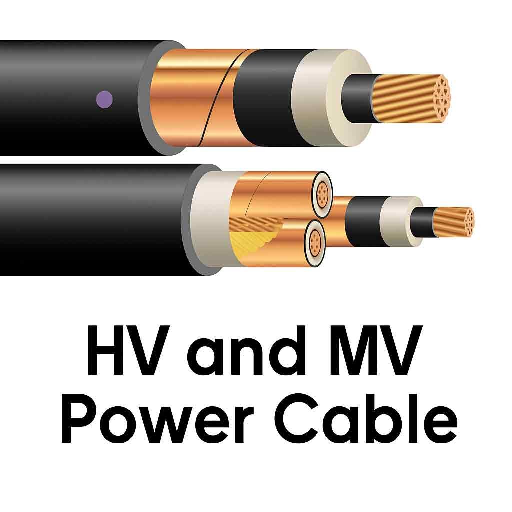
But why do we use these specific numbers, and how do different testing methodologies like DC or standard AC compare? Let’s explore the technical standards and best practices that can save your team from costly electrical breakdowns.
What is the hipot test voltage for 33kV cable according to IEEE 400.2?
Unsure if your testing complies with international standards? Using guesswork for test voltages can lead to rejected commissioning reports or unsafe networks. IEEE 400.2 eliminates this uncertainty by providing clear, standardized voltage levels for testing shielded power cable systems.
According to IEEE 400.2, the recommended VLF (0.1 Hz) hipot test voltage for a 33kV cable (where Uo is roughly 19kV) is typically 57kV RMS (81kV Peak) for installation testing, and 42kV RMS (60kV Peak) for maintenance testing, lasting 15 to 60 minutes.
[image placeholder]
To break this down further, IEEE 400.2 outlines testing parameters based on the cable’s operational phase-to-ground voltage (Uo). For a 33kV system, Uo is calculated as 33kV / √3, which equals approximately 19kV. The standard categorizes tests into three phases: Installation, Acceptance, and Maintenance.
Understanding IEEE 400.2 Test Categories
When power engineering service companies or EPC contractors commission a new substation, they must follow rigorous acceptance criteria. The voltage multipliers change based on the cable’s lifecycle stage.
Test Category | วัตถุประสงค์ | Recommended Voltage Multiplier | VLF RMS Test Voltage (33kV Cable) | Duration |
Installation | After pulling cable, before splicing | ~3Uo | 57 kV | 15 – 60 mins |
Acceptance | After splicing and termination | ~2.5Uo to 3Uo | 47 kV – 57 kV | 15 – 60 mins |
Maintenance | Routine checks on aged cables | ~1.5Uo to 2.2Uo | 29 kV – 42 kV | 15 – 60 mins |
By adhering to these parameters, testing diagnostics teams can accurately assess the health of the insulation. Applying 57kV RMS during the installation phase ensures that any mechanical damage caused during cable pulling is exposed before the system goes live. At KV HIPOT, our VLF Hipot Testers are designed to automatically output these precise IEEE-compliant waveforms, removing the guesswork for site engineers and ensuring your test reports are instantly accepted by local utility companies.
Why is VLF (Very Low Frequency) preferred over DC for 33kV XLPE cables?
Still using traditional DC hipot testers on modern XLPE cables? This outdated practice can silently destroy your cables, leading to catastrophic failure the moment they are re-energized. VLF testing is the modern, safe solution for extruded dielectrics.
VLF (0.1 Hz) is preferred over DC for 33kV XLPE cables because DC testing traps space charges within the extruded dielectric insulation. When the AC operating voltage is restored, these trapped charges cause extreme localized stress, leading to premature insulation breakdown and unexpected cable failure.
[image placeholder]
The shift from DC to VLF testing is a critical evolution in high-voltage electrical testing. Decades ago, DC hipot testers were the industry standard for older paper-insulated lead-covered (PILC) cables. However, the widespread adoption of cross-linked polyethylene (XLPE) cables changed the game entirely.
The Hidden Danger of DC Testing on XLPE
XLPE is an exceptional insulator, but it behaves differently under DC stress. When a direct current high voltage is applied, it injects electrons into the insulation, creating “space charges.” These charges get trapped in the microscopic water trees or impurities within the XLPE layer.
VLF Testing: The Safer Alternative
VLF operates at 0.1 Hz (1 cycle every 10 seconds). It is an AC test, which means the polarity alternates, preventing the accumulation of space charges while continuously stressing the insulation to reveal defects.
คุณสมบัติ | DC Hipot Testing | VLF (0.1 Hz) Testing |
Cable Type Suitability | PILC (Older cables) | XLPE, EPR, and mixed cables |
Space Charge Trapping | High Risk | Zero Risk |
Defect Detection | Poor for water trees | Excellent for water trees/defects |
Post-Test Safety | High risk of breakdown upon re-energization | Safe to re-energize immediately |
As an experienced supplier to power transmission contractors in regions like the Middle East and Southeast Asia, we always advise clients to upgrade their aging DC units to VLF Hipot Testers for their 33kV projects. Not only does VLF protect the cable’s longevity, but it also provides a much more accurate representation of how the cable will perform under actual 50/60Hz AC operating conditions.
What are the standard voltage levels for medium voltage dielectric testing?
Confused by the varying voltage levels across different medium voltage networks? Applying a one-size-fits-all voltage can lead to inadequate testing or severe equipment damage. Knowing the standard levels is crucial for accurate dielectric evaluation.
Standard dielectric testing voltages depend on the system’s phase-to-ground voltage (Uo). For medium voltage networks, test voltages typically range from 2Uo to 3Uo. For an 11kV system, VLF test voltage is around 19kV RMS; for a 33kV system, it is 57kV RMS.
[image placeholder]
Medium voltage (MV) distribution networks typically span from 11kV up to 36kV depending on local grid standards. Testing engineers and utility companies must calculate the correct Uo to determine the appropriate test voltage for a specific network.
Calculating Uo for Medium Voltage Systems
The parameter “Uo” represents the rated RMS power-frequency voltage between each conductor and the grounded sheath. It is the baseline for all dielectric tests. You can determine Uo by dividing the system’s phase-to-phase voltage (U) by the square root of 3 (approx. 1.732).
Quick Reference: MV Dielectric Test Voltages
For EPC contractors and third-party testing services working across different regions, keeping a reference table of VLF test voltages (at 3Uo for installation) is highly efficient.
System Voltage (U) Phase-to-Phase | Phase-to-Ground (Uo) | Recommended VLF Test Voltage (3Uo RMS) | Peak Voltage Equivalent |
11 kV | ~6.35 kV | 19 kV | 27 kV |
15 kV | ~8.7 kV | 26 kV | 37 kV |
22 kV | ~12.7 kV | 38 kV | 54 kV |
33 kV | ~19 kV | 57 kV | 81 kV |
Understanding these voltage levels is vital for equipment selection. When purchasing a VLF Hipot Tester, you must ensure its maximum output capacity comfortably exceeds the required test voltage. For instance, testing a 33kV cable requires an instrument capable of generating at least 80kV Peak. At KV HIPOT, our customized testing solutions guarantee you have the exact output capacity required, whether you are testing an 11kV local grid or a 33kV renewable energy wind farm.
How to define 3Uo RMS voltage for 33kV power cable testing?
Struggling to understand what “3Uo” actually means on your spec sheet? Misinterpreting this formula could mean severely under-testing your network, leaving hidden faults undetected. Properly defining 3Uo is the key to executing a compliant VLF test.
To define 3Uo RMS for a 33kV cable, first determine Uo (phase-to-ground voltage) by dividing the system voltage (33kV) by √3, yielding roughly 19kV. Multiply this by 3 to get 3Uo. Therefore, the required 3Uo RMS test voltage is 57kV.
[image placeholder]
The terminology used in international standards like IEC and IEEE can sometimes be confusing for procurement managers or junior electricians. The “3Uo” metric is a standard multiplier used to ensure the cable insulation can withstand over-voltage events such as switching surges or lightning strikes.
The Math Behind the 3Uo Metric
1. Identify the System Voltage (U): For our scenario, U = 33kV. This is the operating voltage between two phases.
2. Calculate Uo: Cables are tested phase-to-ground. So, Uo = 33kV / 1.732 = 19.05kV.
3. Apply the Multiplier: 19.05kV × 3 = 57.15kV RMS.
RMS vs. Peak Voltage in VLF Testing
One of the most common mistakes field engineers make is confusing RMS (Root Mean Square) with Peak voltage. VLF testing equipment usually displays voltage in Peak values, but standards often refer to RMS.
Voltage Type | Definition | 33kV Cable (3Uo) Value |
RMS (Root Mean Square) | The effective AC voltage | ~57 kV |
Peak | The maximum amplitude of the sine wave (RMS × √2) | ~81 kV |
If your test specification demands 57kV RMS, you must set your VLF tester to 81kV Peak. If you mistakenly set the tester to 57kV Peak, you are only testing at roughly 2Uo, meaning you could miss critical insulation defects. Our KV HIPOT technical engineers always emphasize this distinction during our product demonstrations and remote technical support sessions, ensuring your testing diagnostic teams achieve accurate and reliable results.
What happens if the hipot test voltage is too low on a 33kV power grid?
Are you lowering test voltages to avoid damaging aging cables? Testing at insufficient voltage levels gives a false sense of security, allowing compromised cables to be approved. When these faults trigger under load, the outages are devastating.
If the hipot test voltage is too low on a 33kV power grid , the test fails to stress the insulation enough to expose hidden defects like water trees, partial discharges, or splicing errors. This results in undetected weaknesses that can cause catastrophic operational failures and sudden power outages.
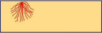
The entire purpose of a high-voltage withstand test is to simulate the most extreme conditions the cable will face during its operational lifespan. Applying a low test voltage completely negates this objective.
The Consequences of Under-Testing
When a 33kV cable is only tested at 1Uo or 1.5Uo, the electrical stress is barely higher than normal operating conditions. Minor defects, poor splice joints, or tracking paths inside the cable termination won’t break down during the test.
Risks to Power Grid Stability
For critical applications like data center power supplies or railway electrical networks, unexpected cable failures cost millions in downtime.
| Risk Factor | Impact of Low Test Voltage | Long-Term Consequence |
| Water Trees | Will not convert to electrical trees | Cable fails months later under standard load |
| Poor Terminations | Weak joints go unnoticed | Arc flashes or fires inside substations |
| Mechanical Damage | Sheath cuts do not trigger a breakdown | Moisture ingress leads to rapid dielectric decay |
Contractors often face pressure to “pass” a cable to speed up project delivery. However, testing diagnostic teams must enforce the 3Uo standard during installation. A controlled breakdown during testing is highly preferable to a sudden explosion during operation. Our advanced VLF equipment is designed to accurately hold these high voltages stably for the required 15 to 60 minutes, giving electrical maintenance teams complete confidence in their infrastructure.
บทสรุป
Ensuring your 33kV cable networks are safely commissioned requires precise voltage application and the right methodology. As dictated by IEEE 400.2, applying a 3Uo VLF test voltage (57kV RMS / 81kV Peak) at 0.1Hz for 15 to 60 minutes is the optimal way to evaluate XLPE insulation without trapping destructive space charges. Whether you are an EPC contractor or a testing laboratory, abandoning outdated DC methods for VLF or AC Resonant solutions guarantees greater grid reliability.
KV Hipot Power Equipment Co.,ltd is ready to supply custom, high-precision testing equipment to safeguard your power infrastructure.

 English
  ไทย
ไทย  Tiếng Việt
  العربية
  Русский
  Italiano
  Español
  한국어
한국어  Português do Brasil
  Français
  Español de México
  Português
  Türkçe
  Čeština
  Español de Argentina
  Slovenčina
  Dansk
Dansk  Polski
  Deutsch
  Ελληνικά
  O‘zbekcha
  Bahasa Indonesia
  Română