This article provides a comprehensive analysis and study of fault diagnosis and treatment of power transformers. Through a detailed discussion of fault types and causes, we identify major fault types such as overheating faults in conducting circuits, degradation of insulation levels, gas-producing faults, regulator switch faults, transformer winding deformation, transformer oil seepage defects, and capacitor bushing faults, and analyze their impact on the safe operation of the transformer

I. Types and Causes of Transformer Failures
1. Conductive Circuit Overheating Faults
Conductive circuit overheating faults are typically caused by poor contact within the transformer’s conductive circuit or substandard welding quality at wire joints. Statistics indicate that approximately 30% of transformer failures stem from this issue. Common problems include overheating of terminal wiring devices and improper soldering of coil wire joints. Additionally, operating under overload conditions can lead to localized overheating, where the transformer load exceeds design specifications. Prolonged overload operation accelerates the aging of the conductor insulation material, increasing the risk of failure.
2. Degradation of Insulation Level
A decrease in insulation level is primarily due to several factors: water and moisture ingress, which diminishes the performance of insulating materials; poor-quality transformer oil, characterized by high dielectric loss, the presence of microorganisms, or excessive water content, all of which adversely affect insulation performance. Research shows that for every 1% increase in dielectric loss of insulating oil, the lifespan of the insulating material is reduced by approximately 10%. Furthermore, localized overheating within the transformer can cause damage and pyrolysis of insulating materials, thereby lowering the insulation level.
3. Gas Production Faults
Gas production faults are generally linked to overheating and electrical discharges. The main causes of overheating include conductor faults, magnetic circuit failures, and subpar connections. Discharge faults can be classified into partial discharges and other types of discharge failures. During the discharge process, excessive electric field strength generates gases that deteriorate insulating materials. Data indicates that discharge faults account for around 15% of transformer failures, and these faults are often challenging to detect using conventional methods, exhibiting a significant degree of concealment.
4. Regulator Switch Failures
Regulator switch failures involve issues such as misalignment of main contacts, loose tap leads, burnt contacts, and inadequate contact pressure. In-load regulator switches may also experience problems, such as poor diverter switch contact, contact burnout, and damaged transition resistors. Statistics show that regulator switch failures constitute about 10% of transformer faults, making them a crucial factor affecting the stable operation of transformers.
5. Transformer Winding Deformation
Transformer winding deformation typically occurs due to improper handling during transportation or insufficient safety measures. In the event of a short circuit, if the transformer has poor short-circuit resistance, the windings may deform or become dislodged, potentially leading to burnout. Fault analysis reveals that approximately 5% of transformer failures are associated with winding deformation.
6. Transformer Oil Seepage Defects
Transformer oil seepage defects include oil leakage from tank welds, high-voltage casing elevated seats, or inlet flanges. These seepage issues not only affect the aesthetics of the transformer but can also lead to internal insulation degradation, potentially resulting in short circuits. According to statistics, oil seepage defects account for about 20% of transformer failures.
7. Capacitor Bushing Failures
Capacitor bushing failures are primarily caused by water and moisture infiltration, poor oil dielectric quality, or overall dielectric loss. Subpar manufacturing quality, significant internal partial discharge, and inadequate grounding of the final screen during operation can lead to compromised insulation or insulation failure of the bushing. While capacitor bushing failures represent about 5% of transformer failures, their occurrence can have serious consequences.
II. Troubleshooting Methods
1. Intuitive Inspection Method
The intuitive inspection method is the preliminary step in diagnosing power transformer faults, relying primarily on the maintenance personnel’s sensory observations, including sight, smell, hearing, and touch. This method is simple and easy to implement, allowing for the quick identification of obvious signs of transformer failure.
Visual Inspection: By examining the external features of the transformer, such as oil seepage, discoloration, and cracks, one can make a preliminary judgment about potential faults. For example, an oil level gauge indicating a significantly lower reading than normal may suggest an internal failure resulting in oil leakage.
Olfactory Inspection: By smelling near the transformer, faults such as overheating or electrical discharge can be detected. For instance, an ozone odor may indicate the occurrence of an external corona or flashover.
Auditory Inspection: By listening to the sounds produced by the transformer during operation, one can determine if there are abnormal vibrations or discharge sounds, which may be caused by poor internal contact or loose parts.
Tactile Inspection: Under safe conditions, touching the exterior of the transformer can help sense abnormal temperature rises, which may indicate internal overheating or a short circuit.
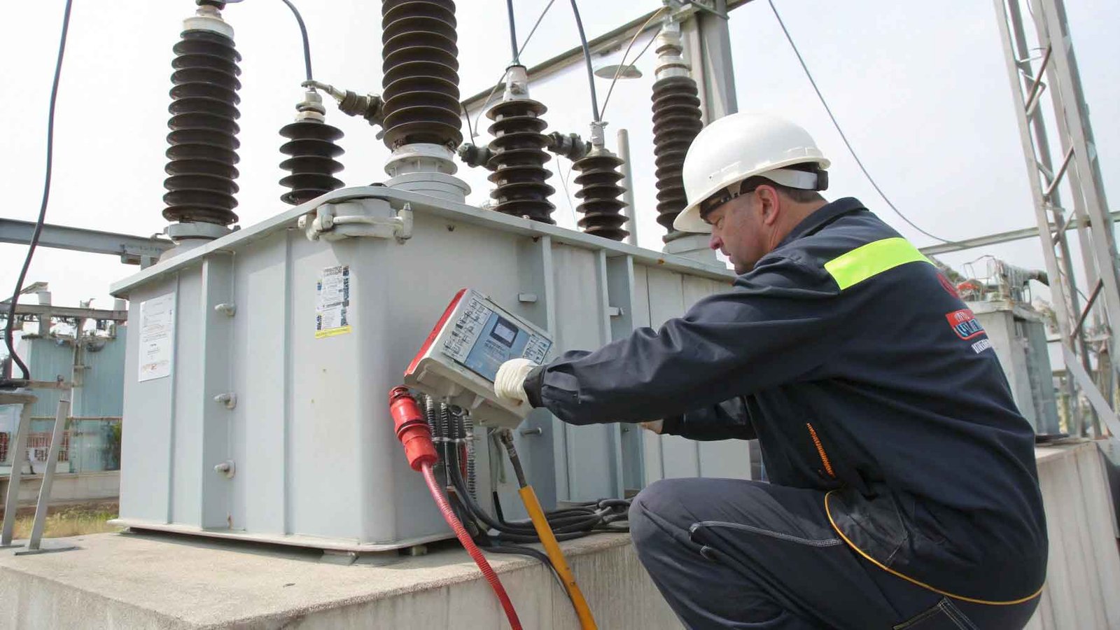
2. Electrical Preventive Test Method
The electrical preventive test method involves a series of tests conducted periodically on power transformers to assess their insulation performance and operational status, thereby preventing failures.
Insulation Resistance Test: This test measures the resistance value of the transformer’s insulation material. A high resistance value indicates good insulation condition, while a low resistance value may suggest that the insulation material is damp or aging.
AC Voltage Withstand Test: By applying an AC voltage higher than the normal working voltage, this test evaluates the voltage withstand capability of the transformer’s insulation materials under over-voltage conditions.
Dielectric Loss Angle Test: This measures the dielectric loss angle of transformer oil and insulating materials. High loss values may indicate defects in the insulating materials.
Partial Discharge Test: This test detects whether there is partial discharge occurring inside the transformer, a key factor leading to the deterioration of insulation materials.
Earth Resistance Test: This measures the resistance value of the transformer’s grounding system to ensure that it can effectively conduct electricity, protecting the transformer from lightning strikes and overvoltage damage.
3. Dissolved Gas Analysis in Oil (DGA)
Dissolved gas analysis in oil (DGA) is a method used to diagnose internal transformer faults by analyzing the composition and content of dissolved gases in transformer oil.
Gas Type Analysis: Through gas chromatography, this analysis detects the levels of dissolved hydrogen (H2), methane (CH4), ethylene (C2H4), acetylene (C2H2), and other gases, which are related to overheating, discharge, and other faults inside the transformer.
Fault Characteristic Gas Discrimination: Specific gases will exhibit characteristic increases based on the type of fault. For example, partial discharge faults can lead to a significant rise in hydrogen content, while arc faults can result in a notable increase in acetylene.
Three-Ratio Method: By calculating the ratios of C2H2/C2H4, CH4/H2, and C2H4/C2H6, this method categorizes and codes the type of fault to determine its nature.
Gas Production Rate Monitoring: This monitors the rate of gas production in the transformer oil, where a rapid increase may indicate the intensification of a fault.
Historical Data Comparison: Comparing the current DGA results with historical data can reveal trends in fault development and provide a basis for early diagnosis of faults.
III. Troubleshooting measures
1 . Treatment of overheating faults
For overheating fault, the treatment measures are mainly focused on improving contact conditions, optimizing wire connections and reducing loads.
Improvement of poor contact: for will army cap wiring device overheating and coil wire joints of the virtual welding problem, first of all, should be thoroughly checked and re-welded to ensure that the connection is firm and conductive. According to the failure statistics, about 30% of the transformer failure originates from the conductive circuit contact malpractice, therefore, the contact point for regular maintenance and inspection is an important measure to prevent overheating failure.
Reduce load operation: For overheating caused by overload operation, the load of the transformer should be reduced immediately to avoid long-term overload operation. At the same time, the cooling system of the transformer should be optimized to improve the heat dissipation efficiency in order to reduce the risk of insulation aging due to overheating.
Increase thermal protection devices: add overheating protection devices in the transformer, such as temperature sensors and automatic circuit breakers, which can cut off the power supply in time and prevent the fault from expanding once the abnormal temperature rise is detected.
2 . Treatment for insulation degradation
Treatment measures for insulation level drop include drying treatment, replacement of insulating oil and repair of insulating materials.
Drying treatment: for transformers with decreased insulation due to moisture, drying treatment should be carried out to remove the moisture in the insulating material. According to research, every 1% increase in dielectric loss value will reduce the life of the insulation material by about 10%, therefore, controlling the moisture content in the oil is the key to maintaining the insulation level.
Replacement of insulating oil: For transformers with poor oil quality, it is necessary to replace the insulating oil with a new one and ensure that the dielectric loss value, moisture content and other indexes of the new oil meet the standards in order to restore the insulating performance.
Repair or replacement of insulating materials: for the damage of insulating materials due to local overheating, the damaged insulating materials should be repaired or replaced in time to prevent further development of the fault.
3.Handling of gas production faults
The treatment measures for gas production faults mainly focus on monitoring and controlling the gas production rate, as well as early diagnosis of internal faults.
Gas production rate monitoring: Through continuous monitoring of the gas in the transformer oil, abnormal changes in the gas production rate can be detected in time, which may indicate the existence of internal faults. Data show that discharge faults account for about 15% of transformer faults, so monitoring the gas production rate is critical for early detection of discharge faults.
Internal fault diagnosis: Utilizing the DGA results, combined with the three-ratio method and other diagnostic techniques, faults such as overheating and discharging within the transformer are accurately diagnosed, and appropriate repair measures are taken.
Preventive maintenance: Regular preventive maintenance of the transformer, including cleaning, tightening connections and checking the condition of the insulation, is carried out to minimize the occurrence of gas-producing faults.
4.Treatment for regulator switch faults
Measures to deal with regulator switch failures include checking and repairing poor contacts, replacing damaged parts and optimizing operating procedures.
Poor contact inspection: For problems such as the main contacts of the regulator switch not being in place and loose tapping leads, a comprehensive inspection should be carried out and poor contact parts should be repaired or replaced. According to statistics, regulator switch failures account for about 10% of transformer failures, so ensuring the reliability of the regulator switch is crucial for the safe operation of the transformer.
Replace damaged parts: Burnt contacts, damaged diverter switches and broken transition resistors should be replaced immediately to restore the normal function of the regulator switch.
Optimize the operating process: Optimize the operating process of the regulator switch to reduce unnecessary operations in order to prolong the service life of the regulator switch and reduce the risk of malfunction.
IV. Failure Prevention and Routine Maintenance

1. Daily Patrol and Inspection
Daily patrol and inspection are fundamental practices for preventing transformer failures. Regular inspections allow for timely identification and resolution of potential faults.
Inspection Content: The inspection should include checking the transformer oil level, oil color, temperature, sound, and smell, as well as evaluating the cleanliness of the transformer, the integrity of grounding, and the condition of attachments. For example, ensure that the oil level in the storage cabinet is normal, the oil level meter is intact and clear, and that any oil in the collection basin is properly drained.
Data Recording: Each patrol should be meticulously documented after inspecting the transformer, noting details such as oil temperature, oil level, and sounds observed. This data is crucial for analyzing transformer performance and preventing failures. Statistics indicate that faults identified through daily inspections account for over 20% of total faults.
2. Regular Inspection and Testing
Regular inspection and testing are vital for ensuring the reliable operation of transformers. Scientific testing methods can be used to evaluate the insulation condition and overall performance of the transformer.
Insulation Resistance Test: According to industry standards, insulation resistance testing should be conducted at least once a year to ensure that the insulation material meets required performance standards. Test results should be compared to previous results, with differences not exceeding 2%.
Dissolved Gas Analysis in Oil: Dissolved gas analysis (DGA) should be performed at least every six months. This analysis helps detect faults such as overheating and discharge within the transformer by evaluating the composition and concentration of dissolved gases in the oil.
Withstand Voltage Test: The withstand voltage test is a key method for assessing the insulation strength of the transformer and should be conducted at least once every three years. This test must be performed when the transformer is offline to ensure safety and accuracy.
3. Failure Prevention Measures
Implementing failure prevention measures is crucial for reducing the incidence of transformer failures. Effective preventive strategies can significantly lower the failure rate.
Load Management: Distribute the load reasonably to avoid prolonged overload operation of the transformer, thereby reducing the risk of insulation aging and failure due to overheating. Statistics show that failures caused by overload operation account for over 30% of total failures.
Temperature Control: Maintain the operating temperature of the transformer within the specified range. Exceeding rated temperatures can accelerate insulation material aging. Optimizing and maintaining the cooling system can effectively regulate the transformer’s operating temperature.
Insulation Monitoring: Regularly monitor the insulation condition of the transformer to detect signs of degradation early. For transformers with compromised insulation performance, timely drying treatment or replacement of insulating oil should be performed to restore insulation properties.
Maintenance: Conduct regular maintenance on the transformer, including cleaning, tightening connection points, and checking the condition of insulating materials. This helps mitigate failures caused by inadequate maintenance. The maintenance cycle should be determined based on the transformer’s operating and environmental conditions, with a general recommendation of at least once a year.
V. Summary
1. Implementation of Troubleshooting Measures
For various types of faults, corresponding treatment measures should be implemented. These measures include improving contact conditions, optimizing conductor connections, reducing loads, performing drying treatments, replacing insulating oil, repairing or replacing insulating materials, monitoring gas production rates, and conducting internal troubleshooting. Implementing these measures is essential for reducing transformer failures and enhancing reliability.
2. Importance of Fault Prevention and Routine Maintenance
The implementation of routine inspections, periodic tests, and fault prevention measures has proven to be effective in preventing transformer failures. These strategies allow for the timely identification and resolution of potential fault hazards, reducing failure occurrences and extending the service life of the transformer.