

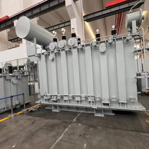
The oil-paper insulation system of a power transformer is continuously exposed to electrical stress, heat, moisture and environmental contamination.
These factors may gradually change the dielectric properties of winding insulation and bushings. Because early-stage deterioration is not always visible, transformer manufacturers and maintenance teams use several electrical and chemical tests to evaluate insulation condition.
Transformer tan delta testing measures two important quantities:
- Dielectric loss tangent, normally expressed as tan δ or tgδ;
- Capacitance of the insulation section under test.
Together, these measurements can help identify changes associated with moisture, contamination, insulation aging, bushing deterioration or changes in insulation geometry.
However, obtaining a reliable result involves more than connecting a transformer tan delta tester and recording a number. Test mode, wiring, voltage, temperature, frequency, grounding and external interference can all affect the measurement.
Este artigo explica o princípio de medição, as ligações GST/UST/GSTg, os procedimentos de ensaio no terreno, a resolução de problemas em caso de resultados anormais e soluções práticas para diferentes ambientes de ensaio de transformadores.
1. Why Is Transformer Tan Delta Testing Necessary?
A transformer may appear normal externally while its insulation is gradually affected by:
- Moisture ingress;
- Thermal aging;
- Oil or surface contamination;
- Long-term electrical stress;
- Bushing deterioration;
- Improper storage;
- Internal insulation damage;
- Mechanical displacement of windings.
Insulation resistance testing is useful for detecting severe leakage and insulation problems, but it does not describe every aspect of dielectric behavior.
Tan delta testing examines the loss characteristics of the insulation under an AC electric field. Capacitance measurement provides additional information about the electrical geometry of the insulation system.
The two measurements should be considered together:
- An increase in tan delta may be associated with higher dielectric losses;
- A change in capacitance may indicate a change in the insulation structure or measuring path;
- A stable capacitance with increasing tan delta may suggest a change in insulation condition without a major geometric change;
- Simultaneous changes in both values may justify additional investigation.
Tan delta testing is commonly used during:
- Transformer factory testing;
- Commissioning and acceptance testing;
- Preventive maintenance;
- Condition-based maintenance;
- Investigation after an abnormal operating event;
- Bushing condition assessment;
- Comparison before and after transformer repair, drying or oil treatment.
A tan delta measurement is not a complete transformer diagnosis by itself. Its value comes from consistent testing, historical comparison and combination with other diagnostic evidence.
2. What Does Tan Delta Actually Measure?
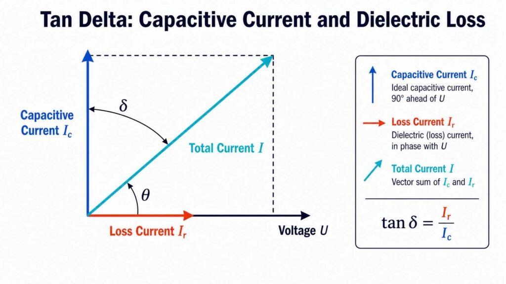
When AC voltage is applied to ideal insulation, the current would be entirely capacitive and would lead the voltage by approximately 90 degrees.
Real insulation is not perfect. Part of the electrical energy is dissipated as heat. The measured current therefore contains two components:
- Capacitive current, Ic: related to energy stored in the insulation;
- Loss current, Ir: related to energy dissipated in the insulation.
The simplified relationship is:

The angle δ is called the dielectric loss angle. Its tangent is used to express dielectric loss.
Tan delta and power factor
Tan delta is also called dissipation factor. Power factor is closely related but is calculated differently.
For a small dielectric loss angle:
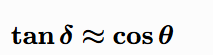
This means tan delta and insulation power factor may have numerically similar values when dielectric losses are low. However, they should not be described as mathematically identical under every condition.
Test records should clearly identify whether the result is:
- Tan delta;
- Dissipation factor;
- Insulation power factor;
- A percentage or a decimal value.
This is especially important when comparing results obtained with different instruments or test procedures.
3. Which Transformer Insulation Sections Are Measured?
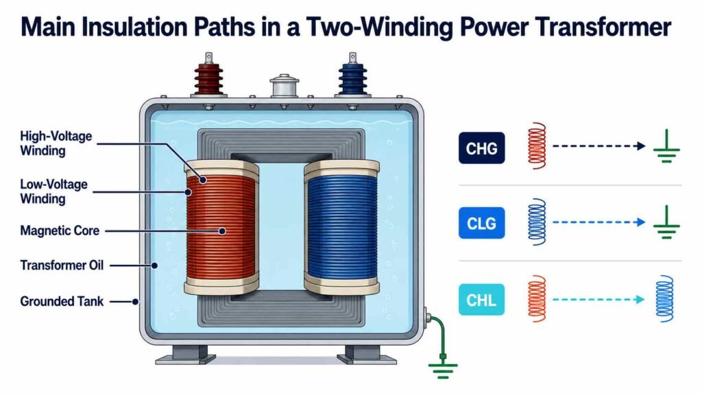
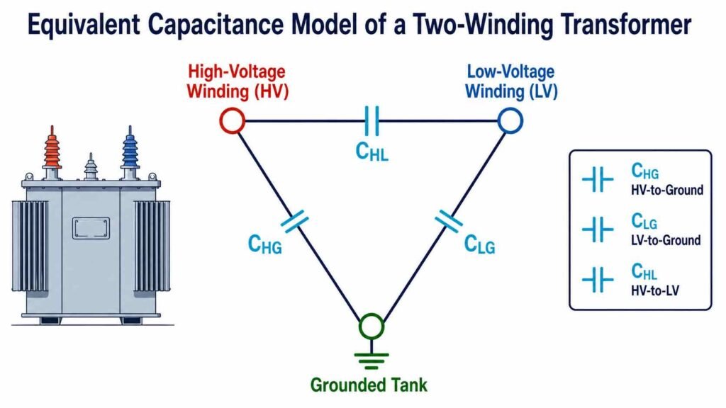
A transformer does not contain one single insulation path. Different winding and grounding configurations create several measurable capacitances.
For a two-winding transformer, the main insulation sections generally include:
- CHG: high-voltage winding to ground;
- CLG: low-voltage winding to ground;
- CHL: high-voltage winding to low-voltage winding.
For a three-winding transformer, additional paths may include:
- High-voltage winding to tertiary winding;
- Low-voltage winding to tertiary winding;
- Tertiary winding to ground.
Bushings may also have their own main insulation and test-tap capacitance.
The purpose of selecting a test connection is to measure the intended insulation section while excluding currents from other sections.
Before testing, the operator should review:
- Transformer nameplate;
- Winding diagram;
- Grounded neutral arrangement;
- Accessible terminals;
- Bushing test taps;
- Manufacturer’s test procedure;
- Asset-owner requirements.
A generic wiring diagram should never replace an approved procedure for the specific transformer.
4. Understanding GST, UST and GSTg Connections
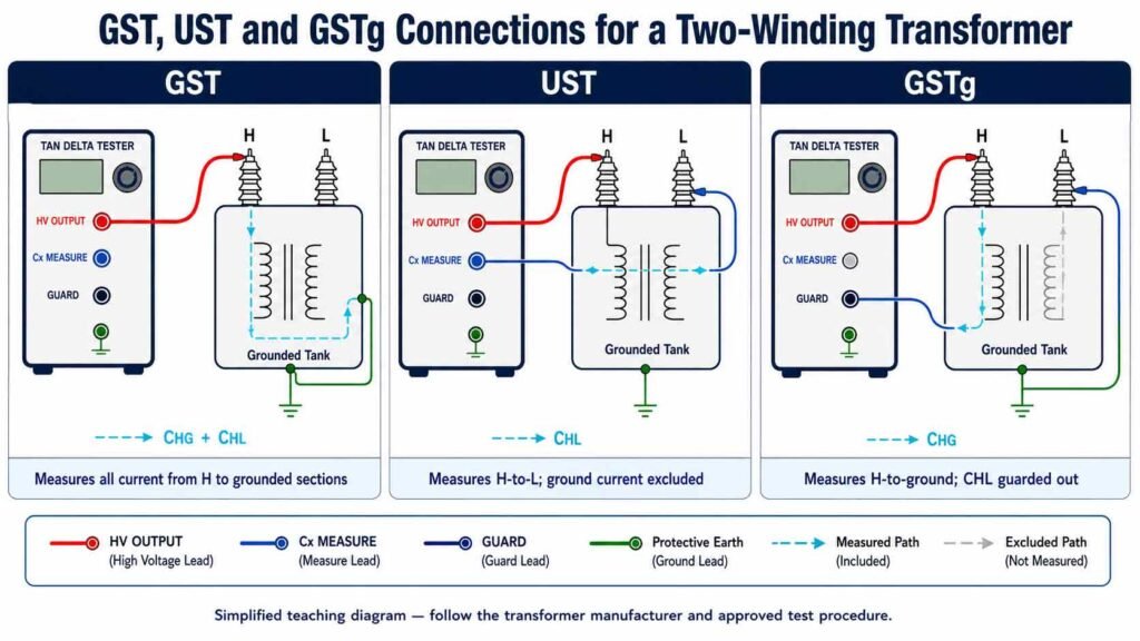
Transformer tan delta testers normally use different measuring modes to include or exclude selected current paths.
GST: Grounded-Specimen Test
GST measures current flowing from the energized terminal through the insulation to ground.
It is generally used when the measured insulation section is grounded or when the total winding-to-ground insulation is required.
In a basic GST measurement:
- One winding is energized;
- The transformer tank is grounded;
- The current flowing to ground is included in the result.
UST: Ungrounded-Specimen Test
UST measures the insulation between two terminals that are isolated from ground. Current flowing to ground is excluded from the measured result.
UST is useful when the operator needs to isolate a winding-to-winding or bushing insulation section.
GSTg: Grounded-Specimen Test with Guard
GSTg measures current flowing to ground while one or more unwanted current paths are connected to the guard circuit.
The guarded current is excluded from the measurement. This makes it possible to separate insulation sections that would otherwise be combined in a standard GST test.
| Test mode | Current included | Current excluded | Typical purpose |
|---|---|---|---|
| GST | Energized terminal to ground | Normally none | Overall grounded insulation |
| UST | Energized terminal to an ungrounded measuring terminal | Current to ground | Winding-to-winding or selected bushing insulation |
| GSTg | Selected energized-terminal-to-ground current | Current connected to Guard | Separation of grounded insulation paths |
5. Practical Field-Testing Procedure
A repeatable procedure is essential for obtaining comparable measurements.
Step 1: Review the transformer information
Record:
- Transformer type;
- Rated voltage and capacity;
- Winding arrangement;
- Vector group;
- Neutral connections;
- Bushing type;
- Previous test results;
- Required test procedure.
Step 2: Isolate the transformer
The transformer must be de-energized, isolated from the power system, discharged and grounded according to the applicable safety procedure.
Disconnect or account for external equipment that may affect the measurement, such as:
- Busbars;
- Cables;
- Surge arresters;
- Neutral-grounding equipment;
- Potential-transformer connections;
- Auxiliary wiring.
Whether a connection must be removed depends on the intended measuring path and approved procedure.
Step 3: Inspect and clean the bushings
Moisture and dirt can create surface leakage currents.
Before testing:
- Inspect the porcelain or composite surface;
- Clean visible contamination;
- Allow wet surfaces to dry;
- Check the condition of bushing test taps;
- Confirm that test-tap covers and grounding arrangements are handled correctly.
Step 4: Record temperature and environmental conditions
Tan delta is temperature-dependent.
Record at least:
- Ambient temperature;
- Transformer oil or winding temperature when available;
- Relative humidity;
- Weather conditions;
- Time since the transformer was de-energized.
If temperature correction is applied, retain both the original measured value and the corrected result.
Step 5: Select the insulation section and test mode
Determine whether the required result is:
- Winding to ground;
- Winding to winding;
- Combined insulation;
- Bushing main insulation;
- CVT C1 or C2 capacitance.
Then select GST, UST or GSTg accordingly.
Step 6: Select an appropriate test voltage
The test voltage must remain within the permitted voltage of the insulation section, bushing test tap and instrument connection.
The highest available tester voltage is not automatically the correct test voltage.
Consider:
- Transformer manufacturer instructions;
- Asset-owner procedure;
- Winding line-to-ground rating;
- Bushing test-tap rating;
- Condition and age of the equipment;
- Purpose of the measurement.
Step 7: Connect the instrument
Confirm:
- Protective earth is connected first;
- The transformer tank is reliably grounded;
- The high-voltage lead has adequate clearance;
- Measuring and guard leads are connected correctly;
- Unused leads cannot contact personnel or grounded structures;
- The test area is controlled.
Step 8: Perform and observe the test
During measurement, observe:
- Applied voltage;
- Test frequency;
- Current;
- Result stability;
- Unexpected noise or discharge;
- Instrument warnings.
If the data is unstable, stop and investigate instead of repeatedly accepting the displayed value.
Step 9: Save the complete result
A useful test record should include:
- Transformer identification;
- Tested insulation section;
- Wiring mode;
- Test voltage;
- Test frequency;
- Measured tan delta;
- Measured capacitance;
- Temperature;
- Humidity;
- Instrument model and serial number;
- Operator;
- Date;
- Notes about disconnected equipment.
Step 10: Discharge before disconnecting
After the test:
- Confirm the high-voltage output is off;
- Allow the instrument to complete its discharge process;
- Apply the approved grounding procedure;
- Verify the absence of voltage;
- Remove the high-voltage lead;
- Remove the instrument earth connection last.
6. Common Abnormal Results and Troubleshooting
An unusual result does not always mean that transformer insulation has deteriorated. The complete measuring circuit should be checked first.
| Abnormal observation | Possible cause | Recommended action |
|---|---|---|
| Result fluctuates continuously | Strong electromagnetic interference | Use variable-frequency measurement and inspect shielding |
| Tan delta is unexpectedly high | Moisture, contamination or external leakage | Clean and dry bushings, then repeat the test |
| Negative tan delta or power factor | Incorrect grounding, Guard error or phantom current | Recheck earth, test leads and selected mode |
| Capacitance is very different from history | Wrong connection or insulation-geometry change | Confirm wiring and compare with other phases |
| Three phases show inconsistent results | Different test conditions or a phase-specific problem | Repeat all phases using identical settings |
| Results are not repeatable | Loose connection or changing temperature | Secure terminals and stabilize test conditions |
| Instrument reports grounding failure | Protective earth is missing or generator neutral is floating | Correct the grounding arrangement |
| Tester cannot reach the selected voltage | Test-object capacitance exceeds the output capability | Reduce voltage if permitted or use a higher-capacity source |
| Reading changes significantly with voltage | Voltage-dependent insulation behavior | Perform controlled voltage-step testing under an approved procedure |
Dealing with field interference
Substation interference can enter the measuring circuit through:
- Adjacent energized equipment;
- Ground potential differences;
- Long test leads;
- Improper shielding;
- Capacitive coupling;
- Power-frequency electromagnetic fields.
A practical interference-control strategy includes:
- Keeping test leads as short as reasonably possible;
- Separating the high-voltage lead from grounded structures;
- Using the supplied shielded measuring cables;
- Establishing one reliable grounding reference;
- Checking Guard connections;
- Using frequencies above and below the system frequency;
- Comparing repeated measurements for stability.
Variable-frequency measurement is particularly useful when testing near a strong 50 Hz or 60 Hz source.
7. How Should Tan Delta Results Be Analyzed?
There is no universal tan delta limit suitable for every transformer, insulation design, test temperature and procedure.
A more reliable assessment uses four levels of comparison.
Level 1: Evaluate the current measurement
Check whether:
- The reading was stable;
- Wiring was correct;
- The test voltage and frequency were recorded;
- Surface leakage was controlled;
- No instrument warning occurred.
Level 2: Compare related insulation sections
Compare:
- Phase A, B and C;
- Similar bushings;
- Corresponding winding insulation paths;
- Results from transformers of the same design where appropriate.
Significant differences should be investigated, but construction differences must also be considered.
Level 3: Analyze the historical trend
A trend from the same transformer is often more informative than comparison with a generic limit.
Historical comparison is meaningful only when the following remain reasonably consistent:
- Test connection;
- Test voltage;
- Frequency;
- Temperature treatment;
- Instrument type;
- External connections;
- Measurement procedure.
Level 4: Cross-check with other diagnostic tests
An abnormal tan delta or capacitance result may justify:
- Insulation resistance and polarization-index testing;
- Transformer-oil dielectric-loss testing;
- Oil moisture analysis;
- Dissolved gas analysis;
- Dielectric frequency-response testing;
- Bushing current or capacitance monitoring;
- Partial-discharge testing;
- Frequency-response analysis;
- Visual internal or external inspection.
The purpose of transformer tan delta testing is not to replace these methods. It contributes one part of a broader insulation assessment.
8. Application Solutions for Different Testing Environments
Solution 1: Transformer factory testing
The main requirements in a transformer factory are repeatability, standardized connections and traceable records.
A suitable workflow should include:
- Defined test templates for each transformer design;
- Standard GST, UST and GSTg connections;
- Controlled test voltage and frequency;
- Automatic recording of tan delta and capacitance;
- Comparison between phases;
- Electronic and printed reports;
- Review of abnormal results before shipment.
The most important goal is not simply completing the test quickly. It is ensuring that every transformer of the same design is tested under comparable conditions.
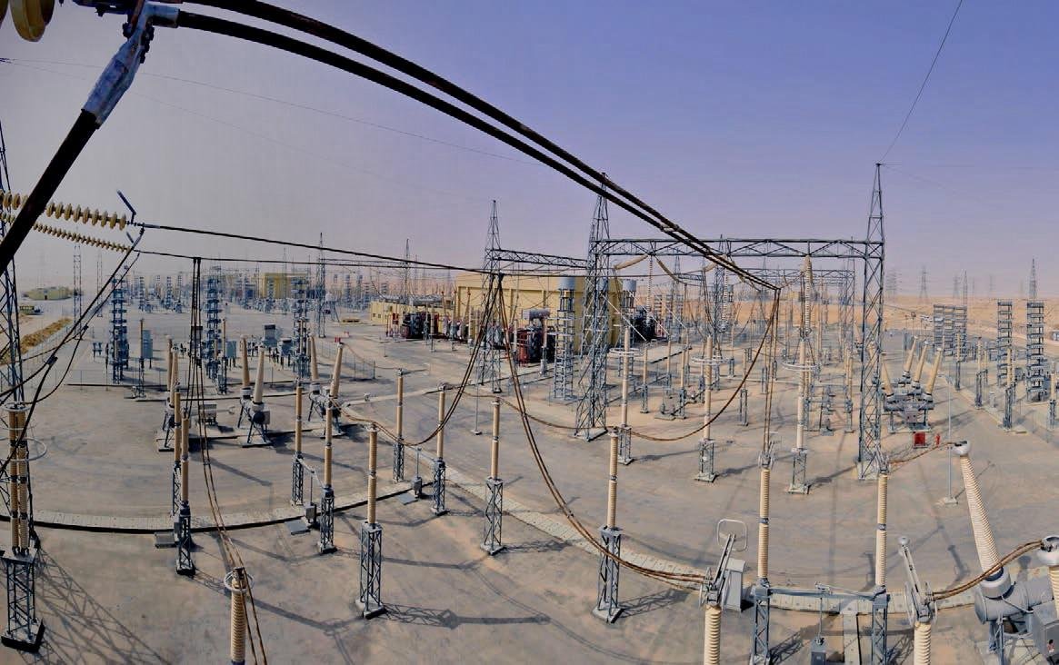
Solution 2: Substation field diagnosis
Field testing introduces additional challenges:
- Strong electromagnetic interference;
- Limited test clearance;
- Ground-potential differences;
- Weather exposure;
- Restricted outage time;
- Different external equipment connections.
The solution should prioritize:
- Variable-frequency anti-interference measurement;
- Reliable grounding supervision;
- Shielded test leads;
- Portable equipment;
- Clear connection guidance;
- Automatic data storage;
- Comparison with previous field records.
Solution 3: Transformer bushing assessment
Bushing tests may involve:
- Main insulation capacitance;
- Tan delta of the bushing insulation;
- Test-tap connections;
- UST measurement;
- Comparison between phases and historical values.
The test-tap voltage rating must be respected. Incorrect handling of a bushing test tap can damage the bushing or create a dangerous condition.
Solution 4: CVT capacitance and dielectric-loss testing
CVT testing may require separate evaluation of C1 and C2 or a combined test.
A suitable field solution may include:
- Separate C1/C2 measurement;
- Simultaneous C1 and C2 measurement;
- Self-excitation testing;
- CVT ratio measurement;
- Shielding arrangements for excluding unwanted current;
- Methods that reduce unnecessary disconnection where approved.
Because CVT internal connections vary, the manufacturer’s diagram and test procedure must be reviewed before selecting the connection.
9. Implementing the Test Solution with the KV-6000A
To perform the workflows described above, a transformer tan delta tester should provide:
- A stable, adjustable AC test source;
- Capacitance and tan delta measurement;
- GST, UST and GSTg configurations;
- Field-interference suppression;
- Grounding detection;
- High-voltage protection;
- Test-data storage;
- Suitable CVT testing functions when required.
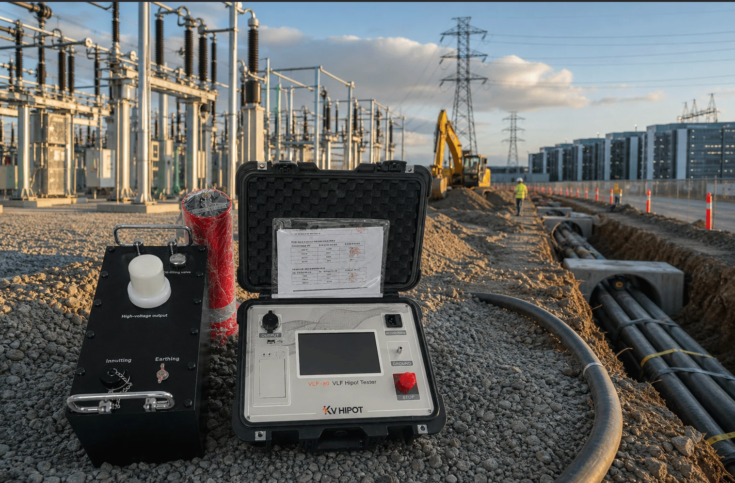
One instrument designed around these requirements is the KV-6000A Transformer Tan Delta Tester from KV HIPOT Power Equipment Co., Ltd.
Transformer dissipation factor capacitance tester KV-6000A combines a built-in high-voltage source, standard measuring loop, digital sampling system and variable-frequency measurement in one field instrument.
Its main solution-related capabilities include:
| Field requirement | KV-6000A implementation |
|---|---|
| Adjustable test voltage | AC 0.5–10 kV internal output; 12 kV optional |
| Capacitive-load capability | Maximum 200 mA output and 2000 VA capacity |
| Interference control | Single- and automatic dual-frequency measurement |
| Insulation-path selection | GST, UST and GSTg test functions |
| CVT testing | Separate, simultaneous, self-excitation and ratio testing |
| Result traceability | Storage of 200 data groups, USB export and thermal printing |
| Grounding safety | Grounding detection prevents normal voltage raising when grounding is improper |
| Equipment protection | Short-circuit, overvoltage, overcurrent and temperature protection |
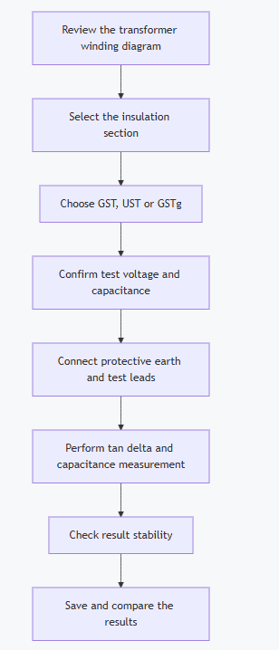
Example test-system workflow
10. Transformer Tan Delta Tester Selection Checklist
When selecting an instrument, buyers should evaluate the complete application rather than focusing only on maximum voltage.
| Selection factor | Question to ask |
|---|---|
| Test voltage | What voltage is required by the approved procedure? |
| Test-object capacitance | Can the instrument supply the necessary current at that voltage? |
| Test modes | Are GST, UST and GSTg all required? |
| Field interference | Can the tester operate above and below the system frequency? |
| CVT application | Are C1/C2, self-excitation or ratio measurements required? |
| Data management | Are local storage, printing and USB export needed? |
| Grounding protection | Does the instrument verify protective grounding? |
| Portability | Can the main unit and accessories be transported safely? |
| Accessories | Are shielded HV, measuring and grounding leads included? |
| Technical support | Can the supplier review the winding diagram and connection plan? |
For the KV-6000A, the test-object capacitance should be checked against the selected voltage:
| Selected voltage | Maximum specified capacitance |
|---|---|
| 10 kV | Below 60 nF |
| 5 kV | Below 150 nF |
| 1 kV | Below 300 nF |
| CVT test | Below 300 nF |
This relationship is important because a high-capacitance test object requires more charging current.
11. Frequently Asked Questions
What is the purpose of a transformer tan delta test?
It measures dielectric losses and capacitance in selected transformer insulation sections. The results help identify changes that may be associated with moisture, contamination, aging, bushing deterioration or changes in insulation geometry.
What is the difference between GST and UST?
GST measures current flowing from the energized terminal to ground. UST measures between two ungrounded terminals and excludes current flowing to ground. GSTg is a grounded test that excludes selected currents through a Guard connection.
Which test voltage should be used?
Use the voltage specified by the transformer manufacturer, asset owner or approved test procedure. The voltage must remain within the permitted level of the winding insulation, bushing test tap and measuring connection.
Why does temperature affect tan delta?
Dielectric-loss behavior changes with temperature. Results measured at different temperatures may not be directly comparable. Record the actual temperature and retain the original result even when temperature correction is used.
Why does the result fluctuate in a substation?
Adjacent energized equipment, ground-potential differences, long leads and capacitive coupling may introduce interference. Check grounding and shielding, shorten leads where practical and use variable-frequency measurement.
What can cause a negative tan delta result?
Possible causes include incorrect grounding, improper Guard connection, external leakage, interference or a phantom-current path. Recheck the complete measuring circuit before interpreting the result.
Does a normal tan delta result prove that the transformer is healthy?
No. Tan delta represents the average dielectric-loss behavior of the measured insulation section. Localized or developing defects may require other tests such as DGA, partial-discharge measurement, dielectric frequency response or frequency-response analysis.
Why should capacitance and tan delta be analyzed together?
Tan delta reflects dielectric losses, while capacitance reflects the electrical geometry and measured insulation path. A change in one or both quantities provides different diagnostic information.
Can the same instrument test transformer bushings?
Yes, if the tester supports the appropriate UST or GST connection and the bushing has an accessible test tap. The bushing manufacturer’s procedure and test-tap voltage limit must be followed.
How often should transformer tan delta testing be performed?
The interval depends on transformer criticality, age, operating history, asset-owner policy and previous results. Testing may also be performed after repair, oil treatment, abnormal operation or a significant change in related monitoring data.
Can a generator power a transformer tan delta tester?
It may be possible if the tester supports generator operation and the generator neutral is grounded correctly. A floating or improperly grounded generator output can trigger grounding protection or affect measurement stability.
12. Conclusion
Reliable transformer tan delta testing depends on the complete measurement process:
- Identify the insulation section;
- Select GST, UST or GSTg correctly;
- Control test voltage and frequency;
- Establish reliable grounding and shielding;
- Record temperature and environmental conditions;
- Verify result stability;
- Compare phases and historical data;
- Use supporting tests when abnormalities are found.
The test instrument is one component of this process. Its output capability, test modes, interference suppression and data-management functions must match the transformer and field environment.
For applications involving complex two-winding or three-winding transformers, bushings or CVTs, KV HIPOT Power Equipment Co., Ltd. can review the equipment diagram and help prepare an appropriate KV-6000A test configuration and connection plan.
Learn more about the KV-6000A transformer capacitance and tan delta tester

 English
  ไทย
ไทย  Tiếng Việt
  العربية
  Русский
  Italiano
  Español
  한국어
한국어  Português do Brasil
  Français
  Español de México
  Português
  Türkçe
  Čeština
  Español de Argentina
  Slovenčina
  Dansk
Dansk  Polski
  Deutsch
  Ελληνικά
  O‘zbekcha
  Bahasa Indonesia
  Română