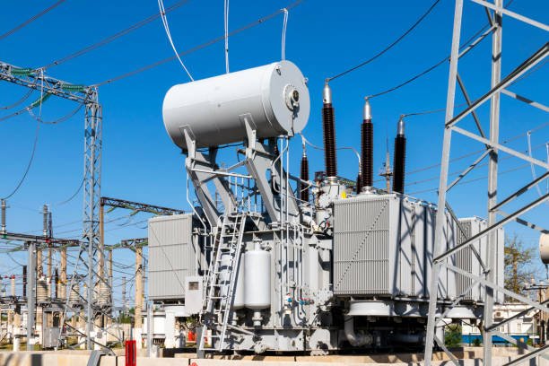
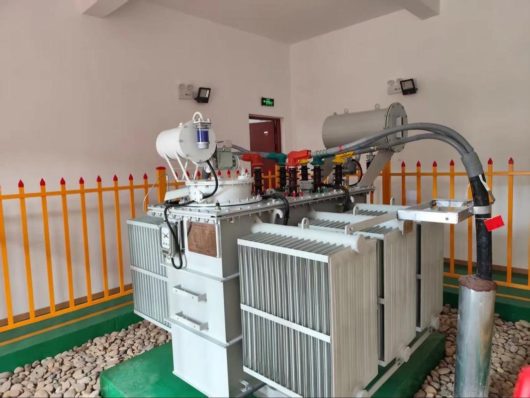
Sweep Frequency Response Analysis (SFRA) test is an important measurement method used to assess the mechanical and electrical integrity of power transformers. It tests the mechanical integrity of transformer cores, windings, and press frames by measuring the voltage transfer function over a wide frequency range. Each electrical network has a unique frequency response called a frequency response fingerprint.
System failures or vibrations can cause changes in the frequency response, and by comparing the frequency response fingerprints of different devices at different times or different equipment, mechanical or electrical changes can be detected.
What issues can SFRA testing detect in transformers?
SFRA analysis is effective in detecting the following major types of problems within a transformer.
- Winding mechanical problems.
- Winding deformations (axial and radial, e.g. hoop buckling, tilting, spiraling).
- Displacement between high and low voltage windings
- Partial winding collapse
- Electrical faults.
- Short-circuit or open-circuit windings
- Core or shield ground faults
- Magnetic Circuit Problems
- Core movement
- Core ground fault
- Structural Problems.
- Clamping structure fracture
- Abnormal internal connections

Here we about about the more detail how SFRA testing can be used to solve the various transformer problems
Winding deformation (axial and radial):
SFRA testing is highly sensitive to changes in the winding structure, which can be caused by various factors such as short-circuit forces, aging, or transportation impacts. When there is axial or radial deformation of the windings, the inductance and capacitance of the windings will change, leading to shifts in the oscillation frequencies and amplitude variations in the SFRA curve.
By analyzing the specific changes in the SFRA signature, engineers can pinpoint the location and extent of the winding deformation. This information is crucial for determining the appropriate maintenance or repair actions, such as tightening the clamping structure or replacing damaged windings, to restore the transformer’s integrity.
Displacement between high and low voltage windings
The relative position of the high and low voltage windings is a critical factor in the transformer’s performance. Any changes in this position, caused by mechanical forces or vibration, will alter the capacitive coupling between the windings. This will manifest as shifts in the peak frequencies and amplitude changes in the SFRA curve.
By comparing the SFRA signature with reference data or a sister transformer, engineers can identify the specific changes indicative of winding displacement. This information helps determine if the winding structure has been compromised and whether corrective actions, such as readjusting the winding positions or replacing the transformer, are necessary to ensure reliable operation.
Partial winding collapse
Partial winding collapse can occur due to various reasons, such as short-circuit forces, insulation deterioration, or mechanical stress. This localized damage to the windings will result in changes in the SFRA curve, particularly in the amplitude of specific frequency bands.
By analyzing the SFRA signature, engineers can detect the presence and approximate location of the partial winding collapse. This information is crucial for planning the appropriate repair or replacement strategy, as partial winding collapse can lead to further deterioration and potential transformer failure if left unaddressed.
Winding short-circuit or open-circuit
SFRA testing is highly effective in detecting winding short-circuit or open-circuit faults. A winding short-circuit will decrease the overall winding impedance, causing a decline in the amplitude of the SFRA curve across a wide frequency range. Conversely, a winding open-circuit will increase the impedance, leading to an overall increase in the SFRA curve amplitude.
By analyzing the specific changes in the SFRA signature, engineers can pinpoint the location and extent of the winding fault, whether it’s a turn-to-turn short, phase-to-phase short, or a complete open-circuit. This information is crucial for planning the appropriate corrective actions, such as winding repair or replacement, to restore the transformer’s functionality and prevent further deterioration.
Grounding fault in the core or shielding layer
Grounding faults in the transformer’s core or shielding layer can significantly affect the SFRA signature. These faults can alter the capacitive coupling between the windings and the magnetic circuit, leading to the appearance of abnormal peaks or distortions in the SFRA curve.
By carefully examining the SFRA data, engineers can identify the specific changes indicative of a grounding fault and determine its location within the transformer. This information is invaluable for troubleshooting and resolving the issue, as grounding faults can compromise the transformer’s insulation integrity and lead to further failures if left unaddressed.
Core movement
Mechanical vibration or movement of the transformer’s core can also be detected using SFRA testing. Changes in the core’s position or condition can affect the magnetic resistance of the magnetic circuit, which will be reflected in the SFRA curve as amplitude variations in specific frequency bands.
By analyzing the SFRA signature, engineers can identify the presence and extent of core movement, which may be caused by issues such as loose clamping structures, core lamination damage, or other mechanical problems. This information is crucial for implementing appropriate corrective measures, such as tightening the core clamping system or addressing any underlying mechanical issues, to ensure the transformer’s structural integrity and reliable operation.
Core grounding fault
SFRA testing can also detect core grounding faults, which can occur due to damage or deterioration of the core’s insulation. These faults can create additional paths for current flow, leading to the appearance of abnormal peaks in the SFRA curve. By analyzing the SFRA signature, engineers can identify the presence and location of the core grounding fault, which is essential for implementing the necessary repairs, such as restoring the core insulation or addressing any issues with the core’s magnetic circuit.
Clamping structure breakage
The clamping structure of a transformer plays a crucial role in maintaining the mechanical integrity of the windings and core. Any damage or breakage in the clamping system can alter the boundary conditions of the windings, leading to changes in the SFRA curve’s frequency characteristics.
By analyzing the SFRA signature, engineers can detect the presence and extent of clamping structure issues, which may include loosening, deformation, or complete breakage. This information is vital for planning the appropriate maintenance or replacement actions to restore the transformer’s structural stability and prevent further deterioration.
Abnormal internal connections
SFRA testing can also reveal issues with the transformer’s internal connections, such as faulty tap changers, terminal connections, or other internal wiring problems. These issues can create additional electrical paths or impedance changes, which will be reflected in the SFRA curve as the appearance of extra peaks or valleys.
By carefully examining the SFRA signature, engineers can identify the presence and approximate location of these internal connection problems, enabling them to take the necessary corrective actions, such as repairing or replacing the affected components, to ensure the transformer’s reliable operation.

Sweep frequency analysis is applied for the following applications when transformer using .
1)After transformer transport
During the transportation process, transformers can be subjected to vibrations and mechanical stresses that may cause damage to the structure.
SFRA can be performed upon the transformer’s arrival at the site to check if the windings have experienced any deformation or displacement. This helps ensure the transformer has not been damaged during transport.
2)After major current faults
When a transformer experiences short-circuit faults or other high-current events, it may lead to winding deformation or insulation damage.
SFRA can detect these mechanical and electrical changes, allowing for early identification of potential internal issues.
3)Before and after major overhaul
Prior to a major overhaul or repair of a transformer, SFRA can be used to obtain the baseline parameters of the transformer.
After the maintenance work, performing SFRA again can verify if the repair has impacted the transformer’s structure. This helps ensure the transformer can operate normally after the overhaul.
4)When potential problems are suspected
If other diagnostic methods indicate the transformer may have some issues, SFRA can provide more in-depth analysis.
What is the IEC Standard of SFRA test?
IEC 60076-18 standard, titled “Power transformers – Part 18: Measurement of frequency response”, provides guidelines and requirements for performing Sweep Frequency Response Analysis (SFRA) on power transformers and reactors.
The key points about the IEC 60076-18 standard for SFRA testing are:
Measurement Scope: The standard covers the measurement of frequency response of power transformers and reactors, including three-phase units, using the SFRA technique.
Test Procedure: The standard outlines the test setup, connection arrangements, and step-by-step procedures for conducting SFRA measurements.
Measurement Frequency Range: The recommended frequency range for SFRA testing is typically from 20 Hz to 2 MHz, though the standard allows for adjustments based on the specific transformer characteristics.
Data Analysis: The standard provides guidance on analyzing the SFRA measurement data, including the interpretation of frequency response curves and identification of deviations or changes compared to reference measurements.
Reporting: Requirements for documenting and reporting the SFRA test results are specified in the standard.
Compared to other traditonal trasnformer dignostic methods such as DGA test (dissolved gas analysis test) and insulation resistance measurement,
SFRA (Sweep Frequency Response Analysis) testing has several key differences and advantages.
- Comprehensive fault detection:
SFRA transformer test can detect a wide range of mechanical, electrical, and magnetic issues within a transformer, including winding deformation, core movement, winding displacement, partial winding collapse, and more. Other methods, such as dissolved gas analysis (DGA) test or insulation resistance test, are typically focused on specific types of faults and may not provide the same level of comprehensive diagnostic information.
- Non-invasive and online testing:
SFRA transformer test can be performed without disrupting the transformer’s operation, making it a non-invasive diagnostic technique. This allows for regular monitoring and early detection of issues, unlike certain offline tests that require the transformer to be taken out of service.
- Sensitivity to structural changes:
SFRA is highly sensitive to changes in the transformer’s winding structure and mechanical integrity, which are not easily detected by other methods. This makes SFRA a valuable tool for identifying subtle issues that may not be apparent through traditional electrical measurements or visual inspections.
- Baseline comparison and trending
SFRA transformer test relies on comparing the current signature with a baseline or reference measurement, often from the factory or a previous test. This allows engineers to detect even minor changes over time, enabling proactive maintenance and preventing potential failures.
- Localization of faults:
By analyzing the specific changes in the SFRA curve, engineers can often pinpoint the location and extent of the identified issues within the transformer, helping to guide targeted maintenance or repair efforts
How does Sweep frequency response analyser work ?
SFRA analyzer will quantify the response changes of internal winding parameters in different frequency domains, and then determine the degree of change of internal windings according to the variables, the amplitude of frequency response change, the area and the trend of frequency response change.

During transformer testing, factors such as inter-turn or inter-phase short circuits, collisions during transport, or coil deformation caused by electromagnetic forces during short circuits and fault conditions can alter the distribution parameters of transformer windings. These changes impact the transformer’s original frequency domain characteristics, resulting in variations in magnitude and shifts in resonant frequency points.
The transformer winding tester, developed based on response analysis methods, is an advanced non-destructive testing (NDT) tool designed to detect internal faults in transformers. It is applicable to 63kV-500kV power transformers.
The transformer winding deformation tester assesses changes in the internal windings by quantifying the extent, magnitude, and location of frequency response variations in different frequency domains. This helps determine the severity of damage and whether significant repairs or overhauls are necessary.

For transformers in operation, comparing the characteristic spectra of a faulty transformer to saved frequency domain characteristics can indicate the extent of the damage. If the original winding characteristics are available, it simplifies the process of analyzing operating conditions, performing post-fault evaluations, and planning maintenance or repairs.
In conclusion ,SFRA testing ensures that transformers remain in optimal condition, ready to deliver reliable performance in the power grid. For utilities and industries relying on these vital components, SFRA testing is an indispensable tool for safeguarding transformer integrity and ensuring uninterrupted power supply.


