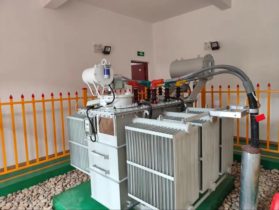
The current electrical test methods for cable cable are diverse and may vary depending on the voltage level and cable type.
This article mainly discusses the test methods of oil-impregnated paper-insulated cables, plastic-insulated cables and cross-linked polyethylene cables, and the common electrical tests include DC withstand voltage and leakage current tests, VLF withstand voltage tests, Power frequency AC resonance withstand voltage testing , partial discharge tests and so on.
At present, the power sector for different voltage levels and types of power cable , the test methods used and the content are different.
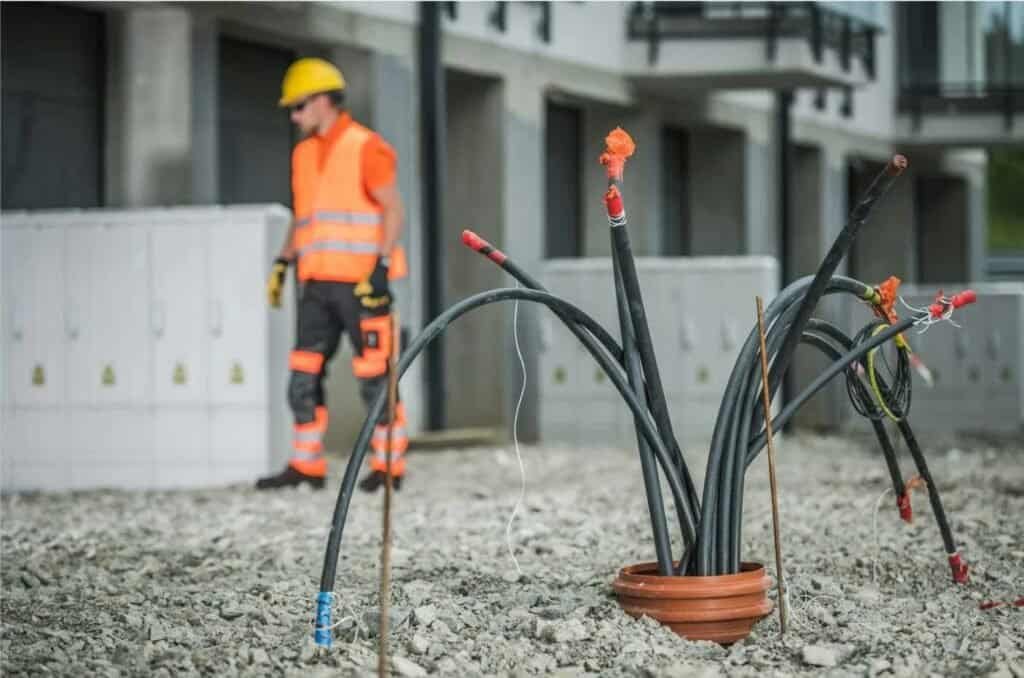
1. DC withstand voltage test for oil-immersed paper-insulated cable
DC voltage testing can effectively reflect the leakage characteristics and voltage behavior of cable insulation. Both theory and practice indicate that the DC and AC voltage characteristics of oil-immersed paper dielectric cables, oil-filled cables, and gas-filled cables are fundamentally similar.
For oil-paper insulated power cables, manufacturers typically conduct routine tests using AC voltage. However, installation and operation units often rely on DC voltage during handover acceptance, preventive testing, or fault repair for several reasons:
- Lightweight Test Equipment: The commonly used DC high voltage generator is portable and suitable for on-site applications. In DC withstand voltage testing, half-wave rectification is typically employed to obtain the test voltage. Multi-voltage rectification technology allows for smaller, lower-capacity test equipment (test transformers and rectifiers) to meet the demands of DC high-voltage testing over longer cable lines.
- Minimizing Insulation Damage: AC withstand voltage tests can cause free discharges within insulation gaps, potentially leading to permanent insulation damage. This risk is significantly reduced with DC withstand voltage tests.
- Measurable Leakage Current: During a DC withstand voltage test, leakage current can be simultaneously measured. By analyzing the leakage current values and their changes over time, one can assess the relationship between leakage current and test voltage, thereby evaluating the insulation condition of the cable.
- Advantages of Negative Polarity Wiring: According to regulations, DC withstand voltage tests utilize negative polarity wiring, meaning the conductor is connected to the negative terminal. If the paper insulation is damp, the presence of positively charged water can lead to a pronounced “electro-osmosis phenomenon” under DC voltage. This effect causes water molecules to migrate from the surface layer towards the conductor (negative), increasing the leakage current and potentially forming penetrating channels, which aids in revealing defects in dampened paper insulation.
- Shorter Pressurization Time: The pressurization time for DC withstand voltage tests is relatively short. For instance, regulations stipulate a pressurization time of 5 minutes for each phase during handover and preventive testing of 6-35 kV cables. This is because the DC breakdown voltage does not significantly vary with pressurization time; typically, defects can be identified within a few minutes of applying DC voltage, eliminating the need for extended pressurization.
The measurement of leakage current during the DC withstand voltage test follows the same principle as insulation resistance testers. However, the applied voltage and instrumentation used in the DC withstand voltage test are generally more precise. Observing changes in leakage current during the pressurization process makes this method more effective at detecting insulation defects compared to standard insulation resistance measurements.
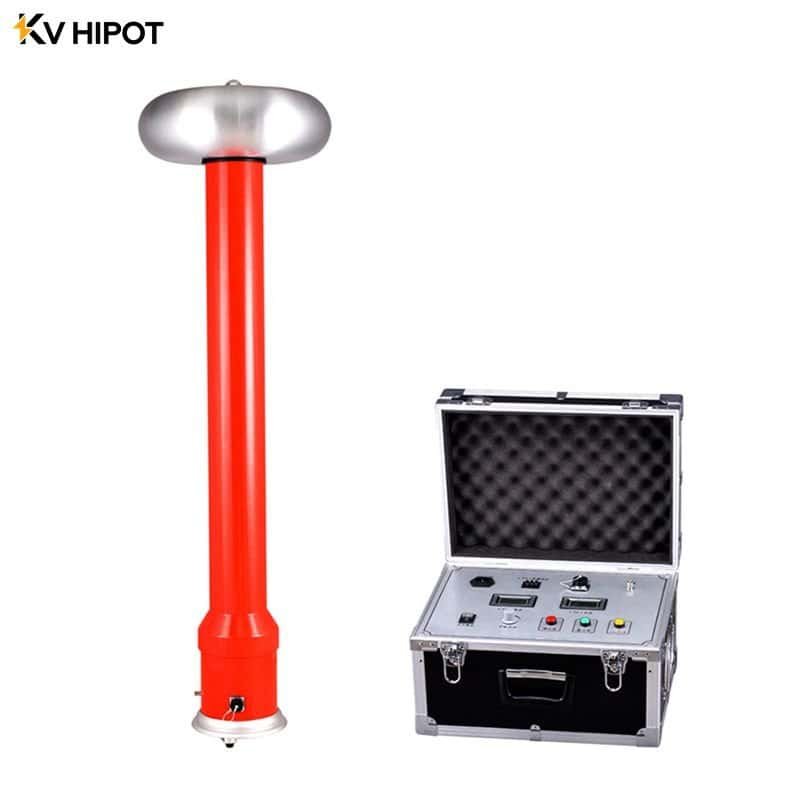
In a DC voltage test, the current flowing through the insulation of a cable consists of the superposition of capacitive current, absorption current, and conduction current. For a cable with intact insulation, the leakage current will decrease and stabilize as the pressurization time increases. In contrast, for cables with poor insulation, the leakage current stabilizes quickly and approaches the initial value. If there are serious defects in the insulation, the leakage current will not decrease over time; instead, it may increase. Prolonging the pressurization time or raising the DC voltage can further elevate the leakage current, potentially leading to insulation breakdown.
To ensure that the measured leakage current accurately reflects the cable’s insulation condition, it’s essential to eliminate the influence of external factors. If the leakage current is unstable, increasing over time or sharply rising with an increase in test voltage, the underlying cause must be investigated.
Typically, the ratio of the leakage current measured before and during the DC withstand voltage test is known as the absorption ratio. For 6 to 35 kV cables, the leakage current before the voltage withstand test is measured at a specified voltage for 1 minute, denoted as I1. The leakage current after the voltage withstand test, measured at the 4-minute mark, is denoted as I2.
For 110 to 220 kV cables, I2 refers to the leakage current measured at the 14-minute mark during the voltage withstand test. According to regulations, the qualification standard for cable leakage tests is that the absorption ratio (I2/I1) must be less than or equal to 1.
2. Withstand voltage test for cross-linked polyethylene cables
At present, cross-linked polyethylene (XLPE) cables are primarily tested using DC voltage. However, the IEC standard clearly stipulates that XLPE cables and their accessories rated above 150 kV should be tested with AC voltage. This involves applying the phase-to-phase voltage of the power system after a 1-hour test or the normal operating voltage after a 24-hour test; DC voltage testing is not recommended.
Since the introduction of high-voltage (110-220 kV) XLPE cables in 1984 and their subsequent import into major cities after 1985, several countries have studied the outcomes of DC voltage tests on high-voltage XLPE cables. These studies have concluded that DC voltage testing is unsuitable for the following reasons:
- Uneven Electric Field Distribution: The electric field distribution within XLPE cable insulation differs significantly between DC and AC voltage. Under DC voltage, the electric field is distributed according to the insulation resistance coefficient, leading to uneven distribution due to the varying resistance coefficients of XLPE insulation. In contrast, under AC voltage, the electric field distributes inversely to the dielectric coefficient. XLPE insulation, which has a dielectric coefficient of 2.1 to 2.3 and is generally stable across temperature changes, maintains a more uniform electric field distribution under AC voltage. Consequently, areas that might be defective under AC voltage may not show issues during DC testing, while those that pass the DC test could fail under AC voltage.
- Accelerated Insulation Aging: If water dendrites are present within the XLPE insulation, their growth is slow under AC voltage but accelerates during the DC withstand voltage test. This can transform water dendrites into electric dendrites, leading to an accumulation effect that accelerates insulation aging and shortens the cable’s service life.
- Formation of Space Charge: During the DC withstand voltage test, space charges can accumulate within the insulation of XLPE cables and their accessories. Continuous formation of these charges may result in breakdown under AC operating voltage, or cause slip flash at the interfaces of accessories due to charge accumulation.
In summary, DC voltage testing is ineffective for detecting insulation defects in XLPE cables and may cause damage that leads to premature insulation breakdown when the cables are re-energized under AC voltage. Therefore, alternative testing methods should be employed for XLPE cables.
2.1 Ultra-Low Frequency Voltage Testing (VLF Testing)
The output frequency of ultra-low frequency AC withstand voltage test devices typically ranges from 0.01 to 0.1 Hz, with a sinusoidal or cosine waveform. This testing method aims to minimize the size and weight of the test equipment while meeting AC voltage requirements. Since DC testing fails to effectively identify defects in XLPE cables and introduces space charge that affects insulation performance, the ultra-low frequency test becomes a suitable alternative.
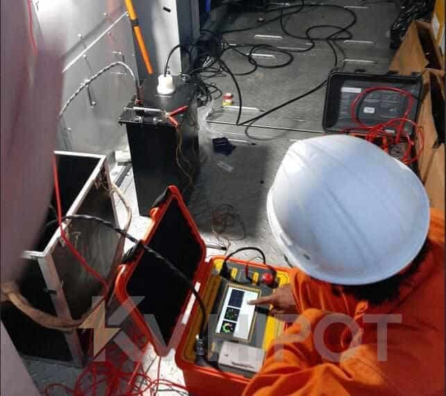
By reducing the frequency from 50 Hz to 0.1 Hz, the capacity of the test equipment can theoretically decrease to 1/500, allowing 0.1 Hz test equipment to achieve similar compactness and portability as DC test equipment, making it suitable for field use. For XLPE power cables, on-site withstand voltage tests should employ a 0.1 Hz ultra-low frequency voltage test, which mainly includes withstand voltage tests and dielectric loss measurements. Currently, international advancements in 0.1 Hz testing equipment are limited to voltages below 100 kV, typically applicable only to medium voltage (6-35 kV) XLPE cable lines, with the recommended testing standard being 3U0/1h.
2.2 AC Resonance Testing
AC resonance testing is a diagnostic method used to evaluate the insulation strength and dielectric properties of electrical equipment, such as transformers, power cables, and switchgear.
This test involves applying a controlled alternating current (AC) at the resonance frequency of the equipment, which allows for high voltage levels to be achieved without requiring excessive power. By doing so, the test can effectively identify insulation weaknesses, defects, or other issues that may not be detectable under standard testing conditions. The results help ensure the reliability and safety of electrical systems, promoting preventive maintenance practices.
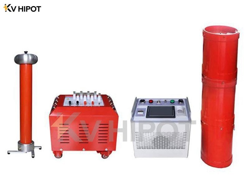
power frequency withstand voltage test most accurately reflects the actual conditions of cable insulation, as the cable operates at this frequency. This makes the test voltage and frequency particularly suitable, allowing for a complete simulation of operational conditions. Theoretically, the intermediate frequency (IF) withstand voltage test not only reveals the leakage characteristics of the cable but also provides a comprehensive view of its voltage characteristics, including localized voltage effects due to dielectric loss.
One of the main challenges in conducting IF AC voltage withstand tests on XLPE cables is the requirement for high-capacity testing equipment; the higher the voltage and the longer the cable, the greater the capacity needed. To address the AC voltage testing needs for XLPE cables in the field, it is crucial to minimize the capacity of the testing equipment. Utilizing series resonance technology is an effective approach to achieve this, as tests have shown that frequency series resonance devices can operate with lower voltage and smaller capacity power supplies, enabling the cable insulation to withstand higher test voltages.
Currently, imported frequency series resonance test equipment includes a fixed inductance reactor operating at 10 to 100 Hz, mounted on a 20-ton flatbed truck, along with a container truck that houses the frequency converter, transformer, and computer control system. This complete setup operates within a frequency range of 30 to 300 Hz, with an output voltage of up to 250 kV and a current of 75 A, making it suitable for conducting AC withstand voltage tests on 220 kV XLPE cables.
3. Partial Discharge Test for Plastic Cables
There are air gaps and moisture in the insulation of rubber-plastic cables. Under rated DC voltage, there is usually only a very short partial discharge process or no partial discharge occurs, while under rated AC voltage, partial discharge may or may not occur. If a partial discharge occurs, the discharge process is short, and the insulation of the cable is usually not penetrated within a certain period of time, but it is very hazardous. Therefore, partial discharge measurements are performed only on specific parts of the cable, such as the suspected part of the cable, intermediate joints, and terminal heads.
Conclusion
For rubber-plastic cables, DC withstand voltage test (DC Hipot Test) can only indicate significant degradation or breakdown of the cable insulation and can have a “destructive” effect, so it should only be used as a last resort and for reference purposes. The ultra-low-frequency high-voltage generator, operated with a control system and high-voltage power supply, is lightweight and easy to use on-site, without causing destructive effects on the cable. This method is suitable for testing rubber and plastic cables but is primarily limited to cables rated at 35 kV or lower due to technical constraints.
AC resonance test system consists of a frequency conversion power supply, excitation transformer, resonant reactor, and voltage divider. While this method is more cumbersome for field operations with cables rated at 35 kV or lower, it can be effectively used for cables rated at 66 kV and above in the field. For cables rated at 110 kV or higher, the oscillating voltage method is compact and easy to operate on-site, but its effectiveness compared to ultra-low-frequency and frequency resonance tests still needs verification.
Partial discharge test can only detect issues in specific areas of the cable, such as intermediate joints and terminals, and is essential for cables rated at 110 kV or higher.
Finally, the dielectric loss measurement method is largely impractical for field use due to its inherent limitations.


