A transformer is a static motor used to transmit alternating current from one circuit to another at a constant frequency through a process of electromagnetic induction. Each transformer is included different accessories , such as iron core , windings , coil, insulation material , tap-changers etc. The transformer windings plays a importance role during the running .
This article will introduce the knowledge about the types , the significance of transformer winding and the transformer winding test

What are transformer windings made of ?
Transformer windings are the most basic component of the transformer, which is the part of the circuit that establishes the magnetic field and transmits the electric power. They are typically wound with copper or aluminum wires wrapped with insulating paper and set on the core column of the transformer. The core of the transformer should have the feature of sufficient insulation strength, mechanical strength and heat resistance
Here is the feature about two kinds of material cooper windings and aluminum windings.
Copper Windings are the most commonly used material for transformer windings.
- It has the high electrical conductivity, which minimizes power losses and improves the transformer efficiency.
- Due to their ability to handle high currents without significant temperature rise, copper windings are suitable for applications with heavy loads.
- The superior thermal conductivity of copper allows for efficient heat dissipation, ensuring the transformer operates within safe temperature limits.
- Provide better performance in terms of electrical conductivity and thermal characteristic, even if Copper windings are more expensive than aluminum windings but .
Aluminum Windings are generally used in large power transformers, where cost considerations are significant.
- Aluminum has a lower electrical conductivity compared to copper, resulting in slightly higher resistive losses.
- To compensate for the higher resistivity, aluminum windings are typically larger in size compared to copper windings.
- The lighter weight of aluminum windings makes them advantageous in applications where weight reduction is a critical factor.
- Aluminum windings have lower thermal conductivity than copper, which may require additional cooling measures to manage heat effectively.
How many windings are in a transformer?
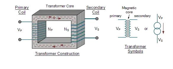
A transformer has two separate windings: the primary winding and the secondary winding.

Primary Winding is the input winding of the transformer, which is connected to the power source. It is designed to receive electrical energy at a specific voltage and current level.
Inducing a magnetic field is the primary winding’s function when alternating current (AC) flows through it.
Secondary Winding is the output winding of the transformer, connected to the load.
The secondary winding receives the magnetic field induced by the primary winding and converts it back into electrical energy at a different voltage and current level than the primary winding.
What is the importance of transformer winding ?

There are several aspects of transformer winding that can be highlighted as being crucial:
Voltage Transformation: Transformer windings facilitate voltage transformation, which is essential for the efficient transmission and distribution of electrical power. By varying the number of turns in the primary and secondary windings, transformers can step up or step down voltage levels, allowing for long-distance power transmission and voltage adaptation to match different load requirements.
Current Transformation: Transformer windings enable current transformation while maintaining the power balance between the primary and secondary sides. This capability is vital for safely delivering electrical energy to various industrial, commercial, and residential applications.
Electrical Isolation: Transformer windings provide electrical isolation between the primary and secondary sides of the transformer. This isolation ensures that electrical energy is transferred from the primary to the secondary side without direct electrical contact. It offers protection against voltage fluctuations, surges, and electrical disturbances, preventing damage to sensitive equipment and enhancing overall system safety.
Power Losses: The design and construction of transformer windings significantly impact power losses within the transformer. Efficient winding design, material selection, and proper insulation help minimize resistive losses (I²R losses) and eddy current losses, leading to improved overall transformer efficiency and reduced energy wastage.
Impedance Matching: Transformer windings help achieve impedance matching between the power source and the load. By adjusting the turns ratio, the transformer can match the load impedance with the power source impedance, optimizing power transfer efficiency and reducing voltage drops.
Overload and Short Circuit Protection: Proper winding design and selection of suitable materials contribute to the transformer’s ability to withstand overloads and short circuits. Transformer windings should be designed to handle high current levels without excessive temperature rise or insulation failure, ensuring reliable and safe operation under abnormal conditions.
Heat Dissipation: Efficient winding design with appropriate conductor size and insulation promotes effective heat dissipation within the transformer. Proper cooling mechanisms, such as oil or air cooling, coupled with optimized winding construction, help maintain the transformer within safe operating temperature limits, ensuring longevity and reliability.
In summary, the importance of transformer winding lies in its ability to provide voltage transformation, current transformation, electrical isolation, and impedance matching. It also influences power losses, protection against overloads and short circuits, and effective heat dissipation. By optimizing transformer winding design, engineers can enhance the performance, efficiency, and reliability of power systems, enabling efficient transmission and distribution of electrical energy.
Why does a transformer winding fail?
Transformer windings can fail due to various reasons, ranging from mechanical stress to electrical and thermal factors. The following are some common causes of transformer winding failures:
Overheating: Excessive heat is a significant factor contributing to winding failures. It can result from high current levels, overloading, poor cooling, or inadequate insulation. Overheating can cause insulation degradation, insulation breakdown, and eventually short circuits or open circuits in the windings.
Electrical Overstress: Voltage surges, transients, or lightning strikes can subject the transformer windings to electrical overstress. These events can cause insulation breakdown, insulation aging, and even insulation punctures, leading to winding failures.
Insulation Deterioration: Over time, the insulation materials used in transformer windings can degrade due to factors such as aging, moisture ingress, chemical exposure, and thermal stress. Insulation deterioration weakens the insulation’s ability to withstand electrical and thermal stresses, increasing the risk of winding failures.
Mechanical Stress: Transformers are subject to mechanical stress during transportation, installation, or operation. Vibrations, impacts, or excessive movement can result in mechanical stresses that can cause winding displacements, deformations, or even shorted turns, leading to failures.
Poor Workmanship: Inadequate manufacturing practices, improper winding techniques, or insufficient quality control can result in winding failures. This includes issues like loose connections, improper insulation application, or inadequate securing of windings, which can lead to hotspots, increased resistive losses, and eventual failures.
Contamination: The presence of contaminants, such as dust, moisture, or conductive particles, can compromise the integrity of transformer windings. Contamination can lead to insulation breakdown, increased leakage currents, and potential short circuits.
Ageing and Wear: Transformers have a finite lifespan, and as they age, the windings can deteriorate. Factors such as thermal cycling, electrical stress, and environmental conditions can contribute to the wear and tear of the windings, increasing the risk of failures.
Overloading and Abnormal Conditions: Operating a transformer beyond its designed capacity or subjecting it to abnormal conditions like frequent voltage fluctuations or overvoltage events can stress the windings, leading to insulation damage, overheating, and ultimately winding failures.
Winding failure is often caused by a combination of factors.There can be several causes of transformer failure, depending on the specific conditions and the type of transformer.
Why do we measure transformer winding resistance ?
Testing the winding resistance of transformers is vital for quality assurance, fault detection, and performance evaluation. It ensures proper manufacturing by verifying connections and resistance values. The variations in resistance enable the identification of faults like open circuits, shorted turns, and loose connections, allowing repair to be done on time.
The test provides insight into winding integrity, identifying conductor damage, insulation deterioration, or loose connections. By comparing resistance values to specifications, performance deviations can be identified and addressed. The measurement serves as a baseline for future comparisons, monitoring changes indicating developing faults or deteriorating conditions. Overall, measuring winding resistance facilitates proactive maintenance, timely repairs, and optimal transformer performance, ensuring reliability and efficiency.

It is important to maintain transformers regularly, monitor their operations, and follow proper maintenance and operating procedures to reduce the risk of winding failures and extend their lifespan. It is essential to proceed the transformer winding testing for regular transformer maintenance
What is the winding resistance test of a transformer ?
The winding resistance test is a diagnostic test conducted on transformer windings to measure the DC winding resistance of transformers and power inductors. This test provides valuable information about the condition of the windings, the integrity of the connections, and the presence of any abnormal resistance that may affect the transformer’s performance.
Winding resistance test of transformer is helpful to assessment of transformer’s condition and performance . Here are the below advance of the winding resistance test .
- Identify faults or abnormalities in transformer windings. It can detect issues such as loose connections, damaged or shorted turns, and open circuits. Early detection allows for timely repairs or maintenance actions, preventing further damage to the transformer.
- Verifying the integrity of transformer windings during installation or after maintenance.
It can detect issues such as loose connections, damaged or shorted turns, and open circuits. Early detection allows for timely repairs or maintenance actions, preventing further damage to the transformer.
- Identify high-resistance connections within the windings. High-resistance connections can lead to increased power losses, overheating, and reduced efficiency. Detecting and addressing these issues can improve the performance and reliability of the transformer.
- Verification of Repairs or Maintenance. After repairs or maintenance activities on the transformer windings, the resistance test can be performed to verify the effectiveness of the undertaken actions. It helps ensure that the repairs were successful in resolving any identified issues and restoring the winding integrity.
- Comparative Analysis. The winding resistance values obtained during routine testing can serve as a baseline for future comparisons. By monitoring and comparing the resistance values over time, it is possible to identify any significant changes or trends that may indicate developing faults or deteriorating conditions.
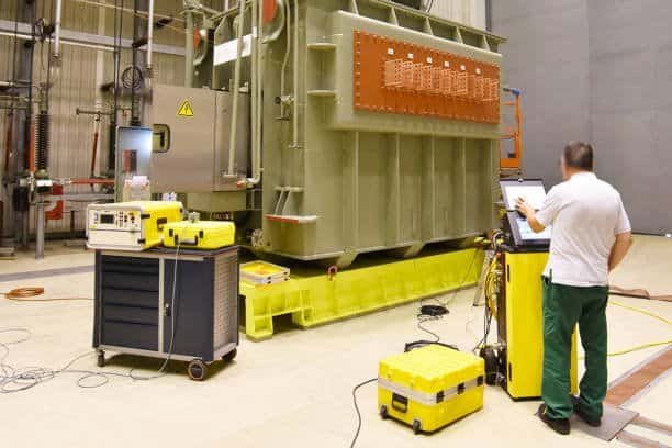
Transformer DC resistance tester of KV Hipot Power Equipment Co.,ltd is the ideal instrument of factory test, installation , exchange the tap-changer in transformer manufacturing and power department preventive test in transformer testing.
It is a cost-effective diagnostic tool that aids in preventing failures, optimizing performance, and extending the transformer’s lifespan.


