

A partial discharge test set combines a high-voltage source with a sensitive measuring circuit to evaluate localized electrical discharges in insulation. Selecting a suitable system requires more than checking its maximum voltage. The test object, capacitive load, background noise, calibration arrangement, and required test sequence all affect whether the results will be useful.
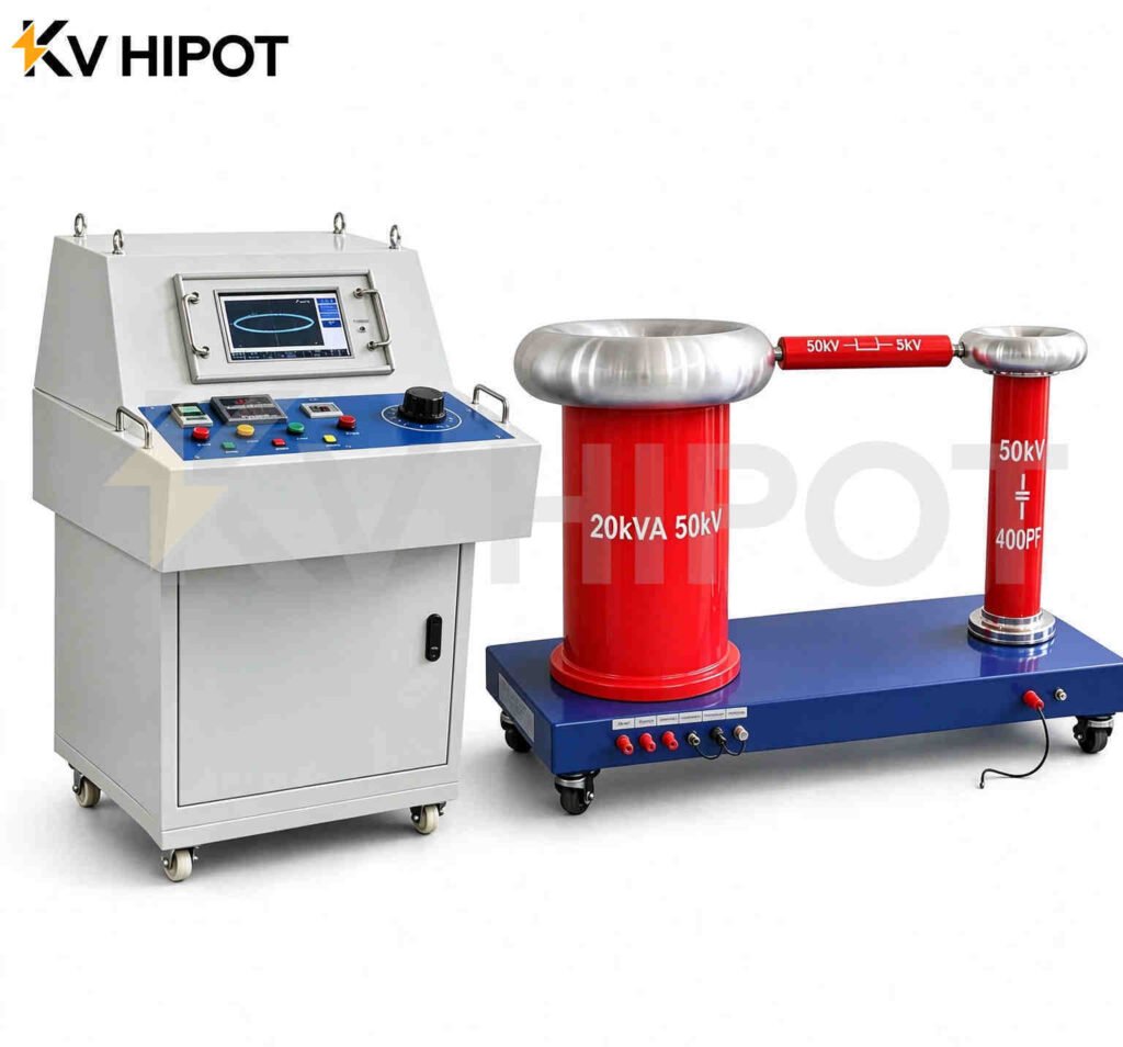
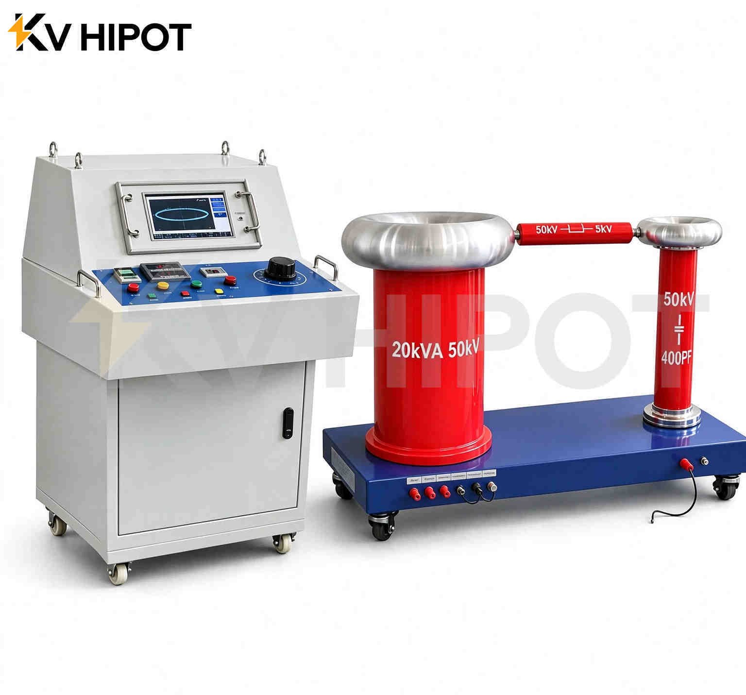
20kVA/50kV power-frequency PD test system brings together an oil-immersed test transformer, automatic control console, digital PD detector, isolation transformer, coupling capacitor, and protective resistor. It is intended for laboratory and factory testing where both AC withstand testing and partial discharge measurement are required.
This guide explains what to check before specifying a system, how to interpret its key ratings, and what information to include in a technical inquiry.
What Does a Partial Discharge Test Set Measure?
Partial discharge is a localized electrical discharge that does not completely bridge the insulation between conductors. Charge-based PD measurements evaluate apparent charge, commonly expressed in picocoulombs, under defined test conditions.
A useful measurement therefore needs more than a displayed pC value. The result must be associated with the applied voltage, measuring circuit, calibration, background noise, and test procedure.
IEC 60270:2025 covers charge-based partial discharge measurements, including measuring circuits, calibration, and discrimination from external interference. The relevant apparatus standard or agreed test specification must also be considered when defining the test and its acceptance criteria. IEC 60270:2025
How to Size a Partial Discharge Test Set: Voltage, Current and Capacitance
Selecting a partial discharge test set starts with the required test voltage, but it cannot end there. The source must also supply the charging current of the connected circuit for the specified test duration, while maintaining background conditions suitable for the required PD measurement.
A 20kVA/50kV system provides a useful starting point for configuration discussions. Whether it suits a particular application depends on the test object, circuit capacitance, voltage sequence, operating duty, and measurement requirements.
Start with the Test Procedure
Before choosing equipment, identify the test object and the test that must be performed.
A transformer, a ring main unit, and a cable may require different connections and procedures. Their operating voltage alone does not determine the required test voltage or confirm that the same source arrangement is suitable.
For transformers, distinguish an applied-voltage test from an induced-voltage test. Do not assume that a single-phase power-frequency source provides every transformer PD test configuration.
Prepare these requirements first:
| Requirement | Information needed |
|---|---|
| Test object | Type, insulation arrangement, and relevant ratings |
| Test Voltage | Maximum voltage, measurement voltage |
| Electrical load | Capacitance or expected charging current |
| Operating duty | Test duration, repetition rate, and cooling intervals |
| PD requirement | Acceptance level and applicable test specification |
| Installation | Supply, space, grounding, and interference conditions |
Calculate the Capacitive Charging Current
For an approximately capacitive load under sinusoidal AC voltage:
I ≈ 2πfCU
Here, I is current in amperes, f is frequency in hertz, C is capacitance in farads, and U is RMS voltage in volts.
At 50Hz and 50kV RMS, the calculated values are:
| Total effective capacitance | Charging current | Capacitive apparent power |
|---|---|---|
| 1nF | 15.7mA | 0.79kVA |
| 5nF | 78.5mA | 3.93kVA |
| 10nF | 157mA | 7.85kVA |
These are illustrative calculations, not guaranteed load ratings. Include the coupling capacitor, relevant stray capacitance, and other circuit contributions when reviewing the complete load.
Interpret the 20kVA/50kV Rating Correctly
Dividing 20kVA by 50kV gives a calculated current of 0.4A. This arithmetic does not replace the manufacturer’s confirmed output-current rating and operating-duty specification.
The transformer, regulator, protection components, measuring circuit, and supply must all support the intended operating condition. Confirm the available output across the required voltage range rather than assuming that full rated kVA is available at every voltage.
Match the Source to the Measurement Requirement
Adequate power does not guarantee an adequate PD measurement.
The assembled circuit must have sufficiently low background interference for the specified acceptance level. Ask for separate statements covering source background, assembled-system background, and measurement conditions with the test object connected.
Request an Application Review
For a 20kVA/50kV configuration review, provide the test-object data, voltage sequence, capacitance, duration, PD limit, and available supply.
If capacitance is unknown, provide the relevant equipment documentation so that the loading requirement can be assessed before configuration approval.
Request a PD test set selection review.
What Is Included in the 20kVA/50kV Configuration?
The proposed configuration combines voltage generation, control, measurement, and protection.
| Component | Function in the system |
|---|---|
| Automatic control console | Controls the voltage sequence and records test information |
| Oil-immersed test transformer | Provides adjustable power-frequency high voltage |
| Digital PD detector | Measures and displays discharge signals |
| Isolation transformer | Provides electrical isolation within the supply arrangement |
| Coupling capacitor | Forms part of the electrical PD measuring circuit |
| Measuring impedance unit | Couples the measurement signal to the detector |
| Protective resistor | Limits current within the specified test-circuit design |
The supplied proposal describes automatic and manual operating modes, programmable test stages, and recording of voltage, time, and discharge information.
The final configuration should be agreed against the actual test object and test procedure. A list of components alone does not establish the achievable measurement sensitivity.
How Do You Select the Required Test Voltage?
Select the output voltage from the required test procedure—not simply from the rated operating voltage of the equipment being tested.
The specification should identify the highest applied voltage, PD measurement voltage, any pre-stress stage, holding times, and the required ramp sequence. These requirements must remain within the approved operating limits of the complete system.
A 50kV source is not automatically suitable for every item in a particular equipment voltage class. The applicable test requirement, insulation arrangement, and test connection must be checked individually.
Detector Sensitivity and Background PD Are Different Specifications
Detector sensitivity describes the measuring instrument. Background PD describes unwanted signals associated with the test arrangement under stated conditions. Neither number alone defines the smallest discharge that can be measured reliably on a connected test object.
The supplied detector specification lists a nominal sensitivity of 0.1pC. That figure should not be presented as a guaranteed 0.1pC measurement capability for the assembled system.
Background performance also depends on the high-voltage source, coupling components, connections, surrounding interference, and test object. Acceptance testing should establish background performance under clearly defined conditions.
When comparing quotations, ask suppliers to distinguish:
| Specification | What needs to be stated |
|---|---|
| Detector sensitivity | Instrument settings and verification conditions |
| Source or component PD level | Applied voltage and test arrangement |
| Assembled-system background | Included components, environment, and measurement settings |
| Measurement capability with the test object | Calibration, interference conditions, and required PD limit |
What Should Be Confirmed Before a PD Measurement?
PD testing should be performed by qualified personnel using an approved high-voltage test procedure and a controlled test area.
Before applying high voltage, the test team should confirm:
- The identity, condition, and intended test connection of the object.
- The required voltage sequence and acceptance criteria.
- The ratings of the source, coupling components, leads, and protective components.
- The approved grounding, isolation, interlock, and discharge arrangements.
- The measuring-system calibration and background-noise assessment.
- The information required in the final report.
Calibration must represent the actual measuring arrangement. Changes to the test object, circuit, or measurement settings may require calibration to be repeated under the applicable procedure.
How Should PD Results Be Interpreted?
A PD result should be interpreted with its test conditions and acceptance specification. A single pC reading does not, by itself, identify the discharge source or establish the remaining life of an insulation system.
Review the measured magnitude together with the applied voltage, repeatability, background level, and available phase-related information. Distinguish signals originating in the test object from interference or external discharge in the test arrangement.
Where required, record partial discharge inception voltage and extinction voltage. These are different observations: one concerns the appearance of detectable PD as voltage increases; the other concerns its disappearance as voltage decreases under the defined procedure.
There is no single pC acceptance limit suitable for every product.
What If the Background Noise Is Too High?
When the background approaches the required acceptance level, first investigate the measurement arrangement before concluding that the test object is defective.
| Observation | Investigation priority |
|---|---|
| Elevated signals before the intended measurement stage | Supply interference, measuring connections, and environmental sources |
| Signals that change with lead position | Coupling from nearby circuits and connection geometry |
| Activity associated with exposed HV connections | External discharge and field-control arrangements |
| Inconsistent readings between repeated tests | Calibration, settings, connections, and test conditions |
| A large change after filtering | Whether useful PD signals are also being suppressed |
Filtering can support analysis, but a quieter display is not sufficient evidence that the measurement has become more accurate. Any filtering or interference-rejection settings that affect interpretation should be documented.
Partial Discharge Testing vs. AC Withstand Testing
| Aspect | AC withstand test | Partial discharge measurement |
|---|---|---|
| Main question | Can the insulation withstand the specified voltage for the required duration? | What discharge activity is detected under specified conditions? |
| Main result | Performance against the withstand requirement | Measured PD information and related test conditions |
| Measurement emphasis | Applied voltage, time, and test outcome | Calibration, background, apparent charge, and signal interpretation |
| Acceptance basis | Applicable apparatus standard or agreed specification | Applicable apparatus standard or agreed specification |
Passing an AC withstand test does not automatically demonstrate compliance with a separate PD requirement. Where both are specified, the test plan must define both assessments.
Preguntas frecuentes
Can a PD detector be used without a high-voltage source?
A detector measures signals; it does not necessarily provide the voltage required for an offline test. Confirm whether the quotation covers only the measuring instrument or the complete test system.
Does a 50kV rating determine which equipment can be tested?
No. Suitability also depends on the required test voltage, load capacitance, current, duration, and test connection.
Does “PD-free” mean that no discharge can ever be detected?
The term should be defined by a specified background or component PD level under stated test conditions. It should not be interpreted as an unlimited zero-discharge guarantee.
Can the same pC limit be used for all test objects?
No. Use the applicable apparatus standard, customer specification, and agreed test procedure.
What information is needed for a quotation?
Provide the test-object type, required voltage sequence, capacitance or charging-current information, test duration, PD acceptance level, power supply, and installation environment.

 English
 ไทย
 Tiếng Việt
 العربية
 Русский
 Italiano
 Español
 한국어
 Português do Brasil
 Français
 Español de México
 Português
 Türkçe
 Čeština
 Español de Argentina
 Slovenčina
 Dansk
 Polski
 Deutsch
 Ελληνικά
 O‘zbekcha
 Bahasa Indonesia
 Română