Failing insulation is a silent threat to any electrical system. This unseen weakness can lead to sudden equipment failure, costly downtime, and serious safety hazards. You need a reliable way to find these problems before they cause a disaster.
An insulation resistance tester, often called a megohmmeter or “Megger,” is a special instrument that checks the quality of electrical insulation. It applies a high DC voltage to the equipment being tested and measures the resulting leakage current to calculate the resistance, helping prevent failures.
Understanding how to properly test insulation is one of the most important skills for any electrical professional. It’s more than just getting a number; it’s about making an informed judgment on the health of your critical assets. I want to share my experience from the factory floor to help you understand the details of this fundamental test, from the circuit inside the device to the standards that give the results meaning. This knowledge will help you keep your electrical systems safe and reliable.
What is an insulation resistance measurement circuit?
It can seem complicated to understand what is happening inside your tester. If you don’t know how the measurement is made, you might not fully trust or correctly interpret the results you see on the screen. The good news is that the core principle is very straightforward.
The circuit is built around two key parts: a stable, high-voltage DC source and a very sensitive current-measuring device (ammeter). The tester applies this known DC voltage across the insulation and measures the small amount of current that leaks through, calculating resistance using Ohm’s Law (R = V/I). At its heart, the insulation resistance tester is designed to do one thing very well: measure extremely high resistance values.
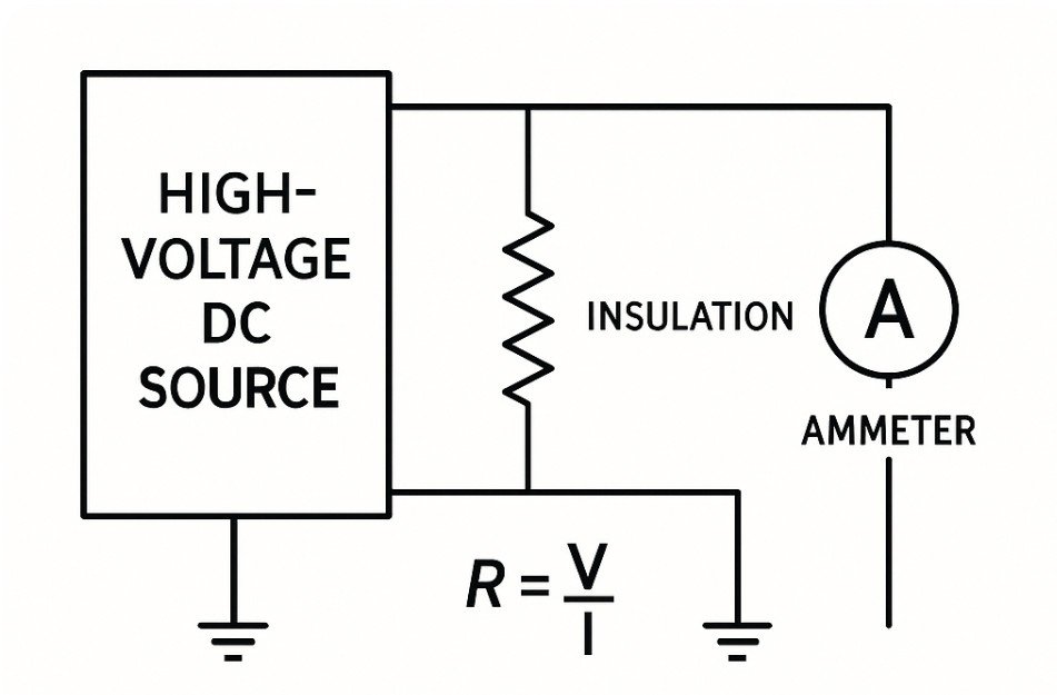
To do this, it needs to be more than just a simple ohmmeter. The DC voltage source has to be very stable, because any fluctuation in voltage would cause an error in the final resistance calculation. The ammeter has to be sensitive enough to measure currents in the nano-amp or even pico-amp range. Many of our high-quality testers also include a “guard” terminal.
This is a critical feature that diverts any surface leakage current away from the main measurement path, ensuring that the final reading represents the true insulation resistance through the material, not just dirt or moisture on its surface.
| Component | Function | Why It’s Important for Accuracy |
|---|---|---|
| High-Voltage DC Source | Provides the stable test voltage (e.g., 500V, 1kV, 5kV). | A stable voltage (V) is essential for an accurate Ohm’s Law calculation (R=V/I). |
| Sensitive Ammeter | Measures the very low leakage current (I) that flows through the insulation. | Must be able to detect nano-amps or pico-amps to calculate high resistance values. |
| Guard Terminal | Provides a separate path for surface leakage current to return to the source. | Prevents surface contamination from affecting the measurement of the true bulk insulation. |
| Calculation & Display Unit | Uses the voltage and current to calculate resistance and shows it on the screen. | Modern digital units provide clear, easy-to-read values in MΩ, GΩ, or TΩ. |
What is an insulation resistance measurement device?
With so many types of testers available, choosing the right one can feel difficult. Picking a device that doesn’t fit your needs can mean wasted money on features you don’t use, or worse, a tester that isn’t powerful enough for your job. The key is to match the device to your application.
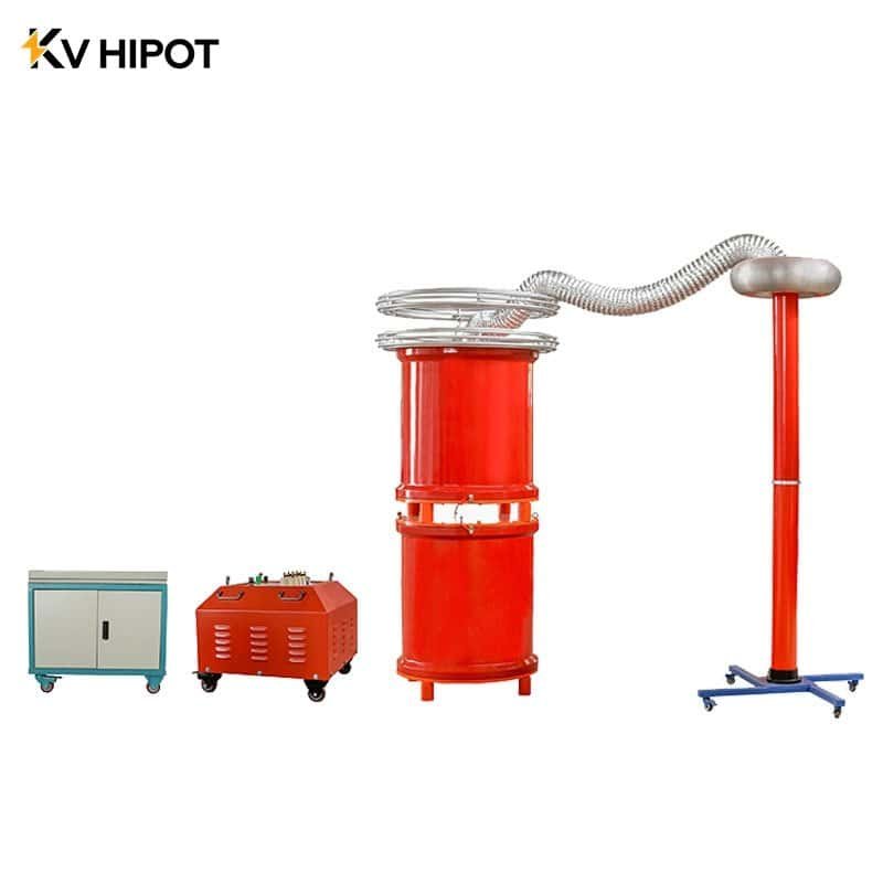
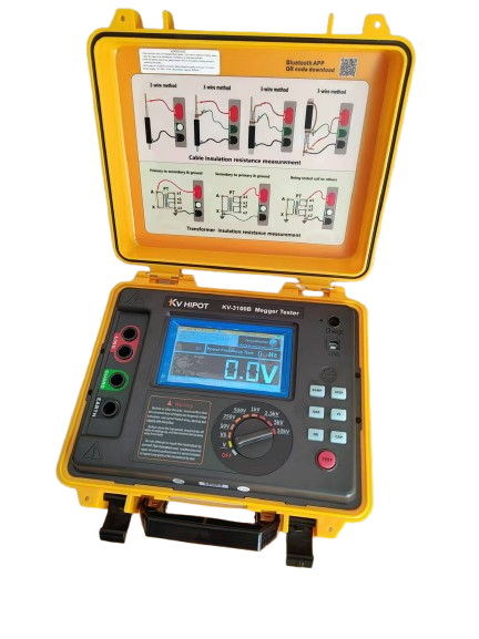
An insulation resistance measurement device is a portable instrument used to perform these tests. They range from small, battery-powered handheld “Meggger” style units for electricians to larger, more powerful benchtop or field testers used for high-voltage equipment like large motors and power transformers.
The right device for you depends entirely on what you need to test. For a residential or commercial electrician, a small handheld megohmmeter with test voltages up to 1000V is usually perfect for checking wiring and small motors. However, for my clients in heavy industry, power generation, or transmission, a more robust device is necessary. These engineers need testers that can output 5kV, 10kV, or even higher to properly test large transformers, generators, and high-voltage cables.
These industrial units, like the ones we manufacture at KV HIPOT, also have a higher power output to charge the large capacitance of these assets quickly, saving valuable time in the field. They also include advanced features like automatic calculation of PI and DAR.
| Device Type | Typical Test Voltage | Best For | Key Features |
|---|---|---|---|
| Handheld Digital Megohmmeter | 250V / 500V / 1000V | General electricians, motor repair shops, residential/commercial wiring. | Small, lightweight, battery-powered, easy to use. |
| Industrial High-Voltage Tester | 1kV / 5kV / 10kV / 15kV | Power plants, substations, industrial maintenance, transformer testing. | Higher voltage/power, diagnostic tests (PI/DAR), durable for field use. |
| Benchtop Laboratory Unit | Variable up to 15kV+ | OEM quality control, research labs, high-precision component testing. | Extremely high accuracy, data logging, programmable test sequences. |
How do you perform an insulation resistance measurement of a transformer?
A power transformer is one of the most expensive and critical assets in any electrical system. An unexpected insulation failure can lead to catastrophic damage, long outages, and incredibly high replacement costs. Regular insulation resistance testing is a simple but vital health check to prevent this.
To measure a transformer’s insulation resistance, you perform a series of tests between the different sets of windings and between each winding and the grounded tank (earth). This process checks the health of the paper, pressboard, and oil insulation system, helping to identify problems like moisture, carbon tracking, or physical aging. Performing the test correctly is crucial for getting meaningful data. Before starting, the transformer must be completely de-energized and isolated, and all terminals must be cleaned to prevent surface leakage from skewing the results.
The standard procedure involves three primary tests to get a complete picture. You test between the high-voltage and low-voltage windings, then you test each winding individually to the grounded tank. By comparing these values to previous tests and to established standards, a maintenance engineer can spot a developing problem long before it leads to a failure. Our transformer testing equipment at KV HIPOT is designed to make this process safe and efficient for field crews.
| Test Connection | HV Lead | LV/Return Lead | Guard Lead | What It Measures |
|---|---|---|---|---|
| High to Low (HV-LV) | HV Winding | LV Winding | Grounded Tank | Resistance of the main insulation between the windings. |
| High to Ground (HV-GND) | HV Winding | Grounded Tank | LV Winding | Resistance of the insulation between the HV winding and the core/tank. |
| Low to Ground (LV-GND) | LV Winding | Grounded Tank | HV Winding | Resistance of the insulation between the LV winding and the core/tank. |
What is an insulation resistance measurement by megger?
You will often hear technicians talk about doing a “Megger test.” This can be confusing if you’re new to the field. Is it a special kind of test? The truth is much simpler: it’s a term that has become a common name for the test itself, based on the original brand that made the tool famous.
“Megger” is a registered trademark of the Megger company, who were pioneers in developing portable insulation resistance testers. A “measurement by Megger” is simply the act of performing an insulation resistance test.
It means using a megohmmeter to apply DC voltage and measure the resistance of the insulation in equipment. While the name “Megger” is famous, the actual process is universal for all brands of insulation resistance testers.
The procedure is a critical safety and maintenance task for any electrical professional. The most important step is always safety: ensuring the equipment is completely powered down and discharged before connecting the test leads. Once connected, the user selects the appropriate test voltage based on the equipment’s rating. Pressing the test button applies the voltage and, after a set time (usually one minute), the resistance value is recorded. This value gives a clear indication of the insulation’s condition.
| Step | Action | Why It’s Important |
|---|---|---|
| 1. De-energize and Discharge | Verify the equipment is off and safely discharge any stored electrical energy. | This is the most critical step for personnel safety. |
| 2. Clean and Connect Leads | Clean the terminals and connect the tester’s leads to the correct points. | Prevents dirt and moisture from causing inaccurate, low readings. |
| 3. Select Test Voltage | Choose a voltage appropriate for the equipment’s rating (e.g., 500V for 480V motor). | Using a voltage that is too high can damage the insulation. |
| 4. Perform the Test | Press and hold the “Test” button for the required duration (typically 60 seconds). | Allows the charging current to stabilize for a consistent and accurate reading. |
| 5. Record and Discharge | Record the resistance value and then safely discharge the equipment again. | The reading is used for maintenance records. Discharging is a final safety step. |
What is the insulation resistance measurement standard?
Getting a resistance reading is just the first step. What does that number actually mean? Without a standard to compare it to, a result of 500 MΩ is just a number. It has no context. Following industry standards is what turns that number into actionable information.
Key international standards, like IEEE 43 for rotating machinery (motors/generators) and IEC 60076-3 for transformers, provide the necessary guidelines. They specify test procedures, appropriate test voltages, and minimum acceptable resistance values for different classes of equipment, ensuring tests are performed safely and consistently.
One of the most important concepts in these standards is temperature correction. The insulation resistance of any material changes dramatically with temperature—a colder winding will show a much higher resistance than a warmer one, even if its condition is identical. For this reason, standards provide tables or formulas to correct all readings to a standard baseline temperature (usually 40°C).
This allows for a true “apples-to-apples” comparison of readings taken over many years, which is essential for tracking the long-term health of an asset. Many of digital testers can even accept a temperature input and perform this correction automatically, making the technician’s job much easier.
| Standard | Applies To | Key Guideline Example |
|---|---|---|
| IEEE 43-2013 | Insulation resistance testing of electric motors and generators. | Recommends a minimum Polarization Index (PI) value of 2.0 for most insulation classes. |
| IEC 60076-3 | Power Transformers – Insulation levels, dielectric tests and external clearances in air. | Specifies the procedure and test voltage levels for routine factory and field tests. |
| NETA ATS-2021 | Acceptance Testing Specifications for Electrical Power Equipment. | Provides minimum acceptable insulation resistance values for nearly all types of electrical equipment. |
What is the insulation resistance measurement method?
Sometimes, just taking a single reading after one minute isn’t enough to tell the whole story. A simple spot test might show an acceptable value, but it could miss the early signs of a developing problem, like moisture or contamination inside the insulation. That’s why we use more advanced diagnostic methods. Beyond the basic spot reading, the two most common and powerful methods are the Dielectric Absorption Ratio (DAR) and the Polarization Index (PI).
These are time-based tests that give a much better insight into the insulation’s quality by watching how the resistance reading changes over a period of up to ten minutes. These methods work because of how different currents behave inside the insulation.
When you first apply the test voltage, a high charging current flows to charge the capacitance of the equipment. Then, a slower absorption current takes over. Finally, only the small, steady leakage current remains. In clean, dry insulation, the absorption current continues for a long time, causing the resistance reading to steadily climb. In wet or contaminated insulation, the high leakage current dominates, and the resistance reading stays flat. The PI and DAR tests capture this behavior as a simple ratio.
Many of our digital insulation testers at KV HIPOT are designed to perform these tests automatically and calculate the ratio, providing a clear pass/fail indicator for the technician.
| Method | Procedure | What It Indicates |
|---|---|---|
| Spot Reading Test | Apply voltage and take a single reading after 60 seconds. | A basic, quick check of the insulation value. Useful for trending over time. |
| Dielectric Absorption Ratio (DAR) | Ratio of the 60-second reading to the 30-second reading (R60 / R30). | Good at detecting moisture and contamination, especially when the test duration is short. |
| Polarization Index (PI) | Ratio of the 10-minute reading to the 1-minute reading (R10 / R1). | The industry-standard test for assessing the long-term health of motor and transformer insulation. |
What is the insulation resistance measurement unit?
When you look at the results from a test, you’ll see units like MΩ, GΩ, and TΩ. It can be confusing, and misinterpreting the unit can make a perfectly good result look terrible, or make a failing result seem acceptable. Understanding these simple prefixes is essential for reading the results correctly.
The base unit for measuring resistance is the ohm (Ω), named after Georg Ohm. However, because we are measuring the resistance of an insulator, the values are incredibly high. To avoid writing out numbers with nine or twelve zeros, we use standard metric prefixes: mega-, giga-, and tera-. Having a tester that can accurately measure across this vast range is critical.
For my clients, a low-voltage motor might be considered healthy with a reading of a few hundred megaohms (MΩ). However, for a large, high-voltage power transformer, we would expect to see readings in the tens or hundreds of gigaohms (GΩ), or even into the teraohm (TΩ) range for a new unit in perfect condition.
A low reading on a transformer that should be in the GΩ range is an immediate red flag. As a manufacturer, we design our KV HIPOT instruments with the sensitivity to provide stable and accurate readings all the way from the MΩ to the TΩ scale, so our clients can trust their results on any type of equipment.
| Prefix | Symbol | Multiplier (in Ohms) | Common Application Example |
|---|---|---|---|
| Mega | MΩ | 1,000,000 (one million) | Standard measurements on motors, generators, and low-voltage cables. |
| Giga | GΩ | 1,000,000,000 (one billion) | High-quality insulation in power transformers, switchgear, and bushings. |
| Tera | TΩ | 1,000,000,000,000 (one trillion) | Very high-performance insulation found in new EHV transformers and lab-grade components. |
Conclusion
The insulation resistance tester is a fundamental tool for predictive maintenance. Understanding how it works, the standards that guide its use, and the methods you can apply is key to protecting your most valuable electrical assets.