

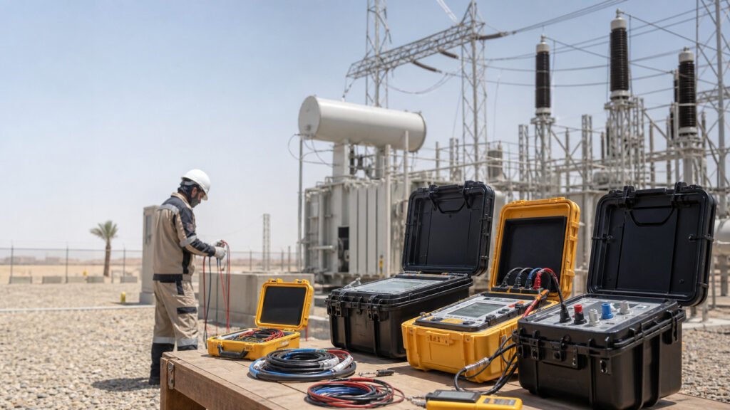
Electrical pre-commissioning verifies that installed equipment is ready for the next approved testing or energization stage. Commissioning verifies that the equipment and interconnected systems perform their intended functions. Commissioning includes activities before energization, during controlled energization, and under operating conditions.
The distinction matters because an installation can pass individual equipment tests and still have an incorrect protection setting, an incomplete trip circuit, or an unsafe switching sequence. Installation completion, acceptable insulation resistance, and successful energization are different milestones. None independently demonstrates that an electrical system is ready for unrestricted service.
For project owners, EPC contractors, and field engineers, the practical question is therefore: What evidence supports the decision to energize this particular system, in its present configuration?
What Is the Difference Between Pre-Commissioning and Commissioning?
Terminology varies between contracts and organizations. Some projects include pre-commissioning within the overall commissioning program; others manage it as a separate phase. The approved project plan should define the boundaries.
| Comparison | Pre-commissioning | Commissioning |
|---|---|---|
| Main question | Is the installation ready for the next approved stage? | Does the system perform its intended functions? |
| Typical focus | Installation condition, connections, equipment checks, and readiness | Functional behavior, protection, interfaces, and operational performance |
| Energy condition | Main power equipment is generally isolated; controlled test supplies may be used | Includes de-energized tests, auxiliary-powered tests, and authorized energized operation |
| Typical evidence | Inspection records and equipment test results | Functional test results and demonstrated system responses |
| Main limitation | Individual equipment acceptance does not prove integrated operation | Successful energization alone does not prove every operating mode |
ANSI/NETA ATS-2025 addresses field inspections and tests for initial energization and final acceptance. ANSI/NETA ECS-2024 addresses electrical commissioning, including system performance verification against project requirements. Their purposes overlap, but equipment acceptance and system performance are not interchangeable. ANSI overview of ATS-2025, NETA ECS-2024 scope
A useful example is a medium-voltage feeder. Its cable insulation may be acceptable, and its circuit breaker may operate mechanically, while a wiring error prevents the protection relay from opening that breaker. Component results can be satisfactory while the feeder’s protective function remains incomplete.
What Should Pre-Commissioning Actually Demonstrate?
Pre-commissioning should produce evidence about the installed asset, rather than simply confirm that a checklist has been signed.
Start with equipment identity and configuration. Nameplate information, voltage ratings, installed accessories, terminal arrangements, and drawings should correspond to the intended application. A correctly tested component installed in the wrong circuit remains an installation problem.
Visual and mechanical checks then address issues that electrical measurements may miss: damaged insulation, loose components, incomplete barriers, incorrect cable support, obstructed operating mechanisms, and unsuitable environmental conditions.
Connection verification requires the manufacturer’s specified method. Bolt torque is not a universal value, and repeatedly tightening a completed joint is not automatically a valid inspection technique. Joint construction, hardware, lubrication, and manufacturer instructions affect the procedure.
Electrical checks should answer defined questions:
| Check | Evidence it provides | What it does not establish by itself |
|---|---|---|
| Continuity | An intended conductive path exists | The connection can carry its required current without excessive heating |
| Insulation resistance | Insulation resistance under the recorded test conditions | Complete dielectric integrity or remaining service life |
| Protective bonding | Required metallic parts are electrically connected | Acceptable step and touch voltages throughout a substation |
| Transformer ratio | The measured transformation relationship matches the selected configuration | Complete winding mechanical or insulation condition |
| Breaker operation | The mechanism responds to specified commands | The complete protection scheme operates correctly |
| Control circuit checks | Defined commands, indications, and connections function | Every integrated operating scenario has been demonstrated |
The outcome should be a clear statement of what has been verified, what remains unresolved, and what activity is permitted next.
Why Insulation Resistance Matters—and Where Its Limits Begin
An insulation resistance test applies a specified DC voltage and evaluates the resulting current. It is useful for identifying an unexpectedly conductive insulation path, but the reading depends on more than the bulk insulation material.
Temperature, moisture, surface contamination, connected equipment, test duration, and the measurement arrangement can influence the result. A low reading is therefore an investigation trigger, not a complete diagnosis.
An interpretable result needs the tested circuit boundaries, test voltage, measurement duration, relevant environmental conditions, and applicable acceptance basis. Without these, two resistance values may appear comparable when they represent different conditions.
A high insulation resistance reading also has limits. It does not replace a specified cable withstand test, transformer diagnostic test, or functional protection check. Different tests challenge different properties.
For MV cables, distinguish insulation resistance testing from a separately specified VLF withstand test. The required waveform, voltage, frequency, duration, and cable condition must be established before selecting the equipment. KV Hipot’s VLF tester product information can support equipment selection, but a product rating does not determine the project’s acceptance test level.
What Should You Do if an MV Cable Has Low IR?
Do not release the affected circuit for energization while an unexplained result remains outside its applicable acceptance requirements.
First establish whether the reading represents the intended cable section. Connected equipment and termination conditions may affect the measurement. Qualified personnel should investigate under the approved isolation and testing procedure.
The investigation may include checking the test arrangement, inspecting accessible terminations, evaluating moisture or contamination, and comparing equivalent phases under comparable conditions. Any corrective work should address an identified cause.
Repeat the required tests after correction. A changed reading should be explainable; repeatedly testing until a favorable number appears does not establish a dependable result.
Why Earthing Verification Requires More Than One Resistance Value
A grounding system cannot be accepted solely because one resistance measurement looks low. Protective bonding, grounding arrangement, fault-current distribution, and accessible voltage differences are related but distinct issues.
For example, acceptable electrode resistance does not prove that a switchgear enclosure is properly bonded. Equally, enclosure continuity does not establish that a substation grounding grid controls step and touch potentials adequately.
IEEE 81-2025 addresses measurement of earth resistivity, grounding impedance, earth-surface potentials, and related measurement limitations. Its scope illustrates why grounding assessment extends beyond a single resistance number. IEEE 81-2025
The applicable installation design should determine which checks and measurements are required. Avoid universal claims such as “every substation must be below 1 ohm” without identifying the governing design criteria.
Grounding should support the intended protection and safety strategy. It should not be described as simply sending all fault current into the soil: the actual return paths depend on the network arrangement.
Protection Relay Testing Must Address the Protection Chain
A relay test can verify selected functions, including pickup, timing, logic, and output behavior. However, a relay response at the test connection does not automatically demonstrate that the associated breaker will interrupt the protected circuit.
The protection chain may include instrument transformers, secondary wiring, relay inputs, settings, programmable logic, auxiliary power, output contacts, trip wiring, trip coils, and the breaker mechanism.
Secondary injection verifies a defined part of that chain. It does not, by itself, prove every upstream primary connection or downstream mechanical response. The commissioning plan must identify which additional checks establish those interfaces.
One useful distinction is between relay operating time и complete fault-clearing time. A relay’s measured response cannot automatically be presented as the total time required for the breaker to clear a fault.
Functional testing should therefore connect the intended initiating condition to the expected system response. Where an actual breaker trip forms part of an approved test, the observation should concern that breaker—not only a relay indication.
These tests use controlled methods. They do not require deliberately creating an uncontrolled fault on an energized installation.
Electrical Interlocks: Verify Both Permission and Prevention
Interlocks restrict operations that are unsafe or inconsistent with the intended switching arrangement. Depending on the equipment, they may be mechanical, electrical, software-based, or a combination.
A useful test verifies two outcomes: the permitted operation succeeds when its prerequisites are satisfied, and the prohibited operation is blocked when they are not.
For example, testing only that a closing command works does not establish that closing is prevented under an excluded condition. Local and remote controls may also follow different paths and should be covered where applicable.
The expected behavior must come from the approved design and manufacturer instructions. An interlock should not be bypassed merely to complete a test or meet an energization deadline.
Interlocks also do not replace isolation, locking arrangements, or verification of electrical condition. Their purpose and limitations must remain clear to operating personnel.
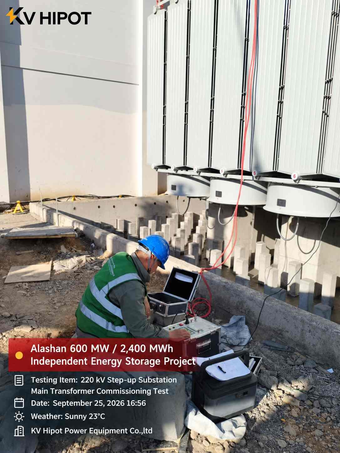
What Must Be Checked Before Energizing an MV Transformer?
Transformer readiness combines the condition of the transformer with the readiness of its connected circuits and protective systems.
The required scope depends on transformer construction, installation history, voltage class, manufacturer instructions, and the approved project specification. Oil-related checks apply to liquid-filled transformers; they should not be copied into a dry-type checklist without adjustment.
Important areas include:
- Installation: correct equipment, clearances, mounting, earthing, cable connections, and accessible terminals.
- Transformation configuration: nameplate voltages, vector group, phase identification, and required tap position.
- Electrical condition: specified insulation, ratio, winding resistance, and other applicable tests.
- Accessories: cooling equipment, temperature devices, alarms, and fitted protective accessories.
- Protection and control: approved settings, auxiliary supplies, trip functions, indications, and relevant interlocks.
- Connected system: cable readiness, surge protection, switching arrangement, and permitted energization boundaries.
Transformer ratio measurements must be interpreted for the actual winding connection and tap position. Line-voltage ratio, phase-voltage ratio, and turns ratio are not automatically interchangeable.
Winding resistance comparisons similarly require consistent measurement conditions and appropriate temperature treatment. A difference should be investigated before being attributed to a winding defect.
Neither a satisfactory ratio result nor an acceptable resistance result establishes complete transformer readiness. Each contributes evidence about a particular aspect of condition or configuration.
Use Numbers to Describe Evidence, Not to Manufacture Confidence
Numerical reporting becomes useful when it reveals a decision, a limitation, or a remaining risk.
Consider this illustrative example, not an actual project record:
| Readiness measure | Example result | Interpretation |
|---|---|---|
| Planned checks completed | 99 of 100 | Work is 99% complete |
| Unresolved energization-critical issues | 1 | A release condition remains unmet |
| Outstanding issue | Breaker fails the required trip test | Protection function is not demonstrated |
| Energization decision | Hold | Completion percentage does not override the failed function |
The calculation is straightforward:
Completion percentage = completed checks ÷ planned checks × 100
But that percentage measures work progress—not electrical safety or commissioning acceptance.
For measurements, present the observed value alongside the applicable requirement and test conditions. “Passed” without those connections provides little technical insight.
For example, a breaker timing result needs to identify the measured operation and applicable acceptance basis. A transformer ratio deviation needs the selected tap and reference ratio. A cable test needs the waveform and test conditions.
Useful results therefore connect four elements:
Tested object → test conditions → measured response → acceptance decision.
This structure makes information easier for engineers to assess and prevents an isolated number from being mistaken for a universal benchmark.
Can Equipment Be Energized With Open Punch-List Items?
Sometimes, but only when the remaining items are compatible with the proposed operating condition and have been accepted through the project’s authorized process.
A cosmetic finish issue may be deferrable. A missing protective bond, unproven trip function, or incorrect switching identification may prevent energization. Classification must reflect the actual consequence, not simply the description assigned in a spreadsheet.
The assessment should consider whether an item affects personnel safety, protection, insulation, equipment ratings, operating access, or reliable identification. Several individually minor issues can also create a significant combined problem.
Formal approval should identify the permitted scope and any operating restrictions. It does not transform an unsafe condition into an acceptable one.
A deferred item also needs a workable completion arrangement. If correction will require another outage, access restriction, or repeat test, that consequence belongs in the decision before energization.
Readiness is configuration-specific. Changes to wiring, settings, connections, or operating boundaries after testing may invalidate part of the previous evidence and require targeted re-verification.
What Happens During Controlled Energization and Operational Verification?
First energization is a controlled transition between operating states. It should follow an approved sequence with defined responsibilities, communication arrangements, observation points, and stop conditions.
Depending on the installation, subsequent verification may examine voltage, phase sequence, indications, alarms, control response, loading behavior, and interactions with connected equipment.
A system that energizes without tripping has demonstrated only that particular event. It has not necessarily demonstrated load transfer, remote operation, loss-of-supply behavior, or every other required mode.
If operating conditions prevent a required test, the limitation should remain visible rather than being treated as a successful result.
Electrical safety obligations also depend on jurisdiction and activity. In the United States, OSHA 1910.269 contains requirements for covered electric-power work, including qualified personnel and controls for de-energization and testing. It is not a universal commissioning procedure for every installation worldwide. OSHA 1910.269
Selecting Test Equipment Around the Required Evidence
For procurement teams, a useful starting point is the test scope, rather than a list of instrument names.
Identify the asset, required test method, operating range, connected load, necessary accessories, and expected output. A tester that reaches the required voltage may still be unsuitable for the connected cable capacitance. An instrument that measures a component may not cover the complete functional test.
KV Hipot Power Equipment Co., Ltd. provides electrical test equipment for applications including cables and transformers. Selection should match the specific commissioning scope, with model capabilities confirmed before purchase. KV Hipot equipment portfolio
The final objective is evidence that supports a defined operating decision. Equipment selection, test execution, interpretation, and authorization all contribute to that outcome.
Frequently Asked Questions
1. Does commissioning begin only after energization?
No. Commissioning includes planning and verification before energization, controlled energization, and applicable operational tests. Many control, protection, and interlock checks can be performed while the main power circuit remains isolated. Contract terminology varies, so the project plan should define the stages and their release conditions.
2. Is a high insulation resistance value enough to energize equipment?
No. Insulation resistance evaluates one aspect of electrical condition under specified conditions. It does not establish correct phasing, protective bonding, transformer configuration, breaker operation, or system protection. Energization requires the complete applicable readiness assessment, rather than one favorable measurement.
3. What is an acceptable insulation resistance value for an MV cable?
There is no single value suitable for every MV cable installation. The acceptance basis depends on the cable system, test method, conditions, manufacturer guidance, and applicable specification. Temperature, circuit length, connected equipment, and termination condition can influence interpretation. Unexplained unacceptable results require investigation before release.
4. What is the difference between relay testing and protection system commissioning?
Relay testing checks selected relay functions under controlled inputs. Protection system commissioning considers the wider arrangement, including measurement inputs, wiring, settings, logic, auxiliary supply, and the intended breaker response. A satisfactory relay test alone does not prove the entire protection chain.
5. Who decides whether an electrical system is ready for energization?
The authority is defined by the project’s operating arrangements, contractual responsibilities, and applicable rules. Test personnel provide evidence, but a test result is not automatically an energization authorization. The designated authority must confirm that required prerequisites are satisfied and that the proposed operating configuration is approved.

 English
  ไทย
ไทย  Tiếng Việt
  العربية
  Русский
  Italiano
  Español
  한국어
한국어  Português do Brasil
  Français
  Español de México
  Português
  Türkçe
  Čeština
  Español de Argentina
  Slovenčina
  Dansk
Dansk  Polski
  Deutsch
  Ελληνικά
  O‘zbekcha
  Bahasa Indonesia
  Română