

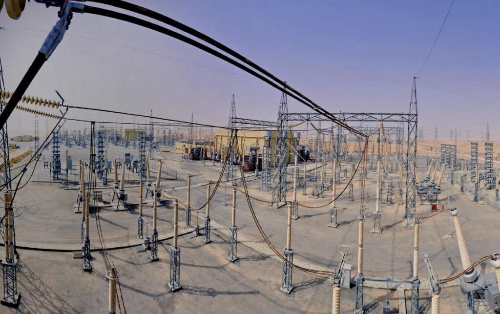
You are conducting a critical hipot test on a 33kV cable, but the voltage keeps dropping unexpectedly. These sudden drops halt commissioning, leaving you frustrated and questioning whether the cable is faulty or your equipment is failing. Time is ticking, and project delays cost thousands of dollars a day. Fortunately, by diagnosing capacitive overloads, ground loop interference, and insulation defects, you can stabilize the voltage and complete your testing successfully.
To fix 33kV cable hipot test voltage drops, reduce the test frequency to 0.05 Hz or 0.01 Hz to lower the capacitive charging current. Additionally, clean all terminations to prevent surface leakage, eliminate ground loop interference, and ensure your VLF tester’s load capacity matches the cable length. [image placeholder] Facing a fluctuating test voltage is a common roadblock that demands immediate and precise troubleshooting. Let’s explore the exact steps you must take to overcome these testing hurdles and confidently verify your electrical infrastructure.
How to fix voltage drop issues when testing long runs of 33kV cable?
Testing miles of underground 33kV cable often results in severe voltage drops. This frustrating issue prevents you from reaching the required 57kV RMS target, threatening your project handover. Adjusting your testing parameters is the key to maintaining a stable voltage. To fix voltage drops on long 33kV cables, decrease the VLF test frequency from 0.1 Hz to 0.05 Hz or 0.01 Hz. This reduces the capacitive charging current demand, allowing your VLF tester to reach and maintain the 57kV RMS target without overloading. [image placeholder]
The Physics Behind Capacitive Loading
When testing long underground runs of 33kV cable, the high capacitance acts as a massive energy sink. Standard VLF (Very Low Frequency) testers are designed to push alternating voltage across this capacitive load. However, as the physical length of the cable increases, the total microfarad (μF) capacitance scales linearly.
Adjusting Frequency to Stabilize Voltage
If your tester maxes out its current output, the voltage will inherently drop or fail to climb. The solution lies in the relationship between frequency, capacitance, and current. Lowering the frequency gives the equipment more time to charge the cable during each half-cycle.
| VLF Test Frequency | Charging Current Demand | Ideal 33kV Cable Length |
| 0.1 Hz | 높음 | Short runs (Up to 2 km) |
| 0.05 Hz | 중간 | Medium runs (2 km to 5 km) |
| 0.01 Hz | Low | Long runs (Over 5 km) |
What to do if the cable capacitance exceeds your VLF tester’s maximum load?
An overload warning flashes on your tester because the cable is simply too long. This bottleneck halts testing completely, leaving you with untested infrastructure. Using the right equipment strategies will bypass this capacitive limitation. If the cable capacitance exceeds your VLF tester’s maximum load, lower the frequency to 0.01 Hz to increase the load capability. If it still exceeds limits, test the cable in shorter, sectioned lengths or upgrade to a higher-capacity VLF tester equipped for heavy loads. [image placeholder]
Identifying Capacitive Overload
Every VLF tester has a maximum capacitive load limit, typically measured in microfarads (μF). When a 33kV cable network—such as those found in massive offshore wind farms or large industrial parks—surpasses this limit, the machine cannot supply enough current to raise the voltage. The tester will either trip on overload or display a continuous voltage drop.
Practical Field Solutions for Overloads
Field engineers have three primary workarounds when facing this limitation. The first, as mentioned, is reducing the frequency. However, if the cable is exceptionally long and still exceeds the 0.01 Hz capacity limit, you must physically alter the test setup.
| Strategy | Implementation Method | Pros & Cons |
| Frequency Reduction | Change tester settings to 0.01 Hz. | Fast and easy, but testing takes longer. |
| Sectional Testing | Open splice points and test segments individually. | Guarantees testing, but requires splicing labor. |
| Phase-by-Phase | Test one phase while grounding the others. | Reduces overall capacitance vs three-phase testing. |
How to resolve ground loop interference during leakage current measurement?
Erratic leakage current readings and unpredictable voltage drops can ruin a hipot test. These parasitic ground loops create false failure signals, causing you to doubt a perfectly healthy cable. Proper grounding techniques instantly clear up this electromagnetic confusion. To resolve ground loop interference, ensure your VLF tester and the 33kV cable shield share a single, common ground point. Avoid multiple grounding paths, use shielded measurement cables, and isolate the termination ends from adjacent grounded metal structures to stabilize readings. [image placeholder]
The Hidden Threat of Ground Loops
When conducting precision high-voltage tests, your equipment measures microamps of leakage current to determine insulation health. Ground loop interference occurs when multiple grounded points have slightly different potentials, causing unintended current to flow through your measurement circuits. This parasitic current distorts readings and can even trigger false voltage drops on the VLF display.
Establishing a Single-Point Ground System
In complex environments like electric substations or heavy manufacturing plants, stray currents are everywhere. To get an accurate reading and maintain test voltage, field technicians must eliminate alternate earth paths.
| Grounding Best Practice | 목적 | Result on Test |
| Single-Point Grounding | Connect tester ground and cable shield to one central earth spike. | Eliminates voltage potential differences. |
| Shielded Test Leads | Use factory-supplied, shielded high-voltage output cables. | Blocks ambient electromagnetic interference (EMI). |
| Termination Isolation | Keep cable ends suspended away from substation racks. | Prevents stray surface current leakage. |
Why does the test voltage fluctuate erratically on aged 33kV power cables?
Testing older 33kV cables often yields bouncing, unstable voltage readings. This erratic behavior makes it impossible to verify network safety, raising fears of an imminent blowout. Identifying the root cause within the aged insulation helps you make informed maintenance decisions. Test voltage fluctuates on aged 33kV cables due to internal partial discharge (PD) within water trees, degraded splices, or tracking across contaminated terminations. These micro-arcs cause temporary voltage collapses, signaling that the XLPE insulation is severely compromised and nearing a complete failure. [image placeholder]
Understanding Micro-Arcing in Aged XLPE
Unlike a solid dead short that immediately trips the hipot tester, fluctuating test voltages indicate a dynamic, intermittent fault. In aged 33kV underground networks—especially those in damp environments like water utilities or older industrial plants—moisture ingress creates microscopic “water trees” within the polymer. Over time, these evolve into electrical trees.
How Partial Discharge Causes Voltage Instability
When the VLF tester applies 57kV RMS, the intense electric field causes these internal voids and degraded joints to briefly arc. Each micro-arc acts as a momentary short circuit, draining high-voltage energy and causing a micro-drop in the tester’s output voltage. The tester’s power supply immediately compensates, causing the voltage to bounce erratically.
| Fluctuation Pattern | Probable Cause | Recommended Diagnostic |
| Rapid, small bouncing | Internal partial discharge in cable voids. | Conduct a PD mapping test. |
| Slow, sweeping drops | Severe moisture ingress in a field splice. | Use Tan Delta (TD) diagnostics. |
| Sudden, large spikes | Surface tracking on a dirty termination. | Visually inspect and clean terminations. |
For transmission and distribution companies, relying solely on a simple withstand test is no longer enough for aging infrastructure. If you observe these voltage fluctuations, it is highly recommended to pair your KV HIPOT VLF system with Tan Delta and Partial Discharge accessories to evaluate the exact severity of the degradation before the cable violently fails in service.
How to safely mitigate space charge accumulation after an accidental DC hipot test?
Accidentally applying a DC hipot test to an XLPE cable injects dangerous space charges. If re-energized immediately, these trapped charges can violently rupture the insulation, causing catastrophic failure. You must safely neutralize this energy before returning the cable to service. To mitigate space charge accumulation after an accidental DC hipot test, solidly ground the 33kV cable conductors and shields for at least 24 to 48 hours. Alternatively, performing a prolonged 0.1 Hz VLF test can help dissipate the trapped charges safely through alternating polarity. [image placeholder]
The Dangers of DC Testing on XLPE
While DC testing is perfectly fine for old paper-insulated lead-covered (PILC) cables, it is highly destructive to modern extruded dielectrics like XLPE. A direct current test forces electrons deep into the microscopic voids of the polymer, creating “space charges.” When the 50/60Hz AC grid voltage is restored, the trapped DC field conflicts with the alternating AC field, creating extreme localized voltage stress that often leads to immediate insulation puncture.
Safe Discharge and Mitigation Protocols
If a contractor unknowingly uses an outdated DC tester on a 33kV XLPE line, immediate corrective action is mandatory to save the asset. The goal is to allow the trapped electrons to migrate out of the insulation naturally.
| Mitigation Step | Action Required | 목적 |
| 1. Hard Grounding | Apply solid earth grounds to all phase conductors. | Provides a path for surface charges to bleed off. |
| 2. Rest Period | Leave the cable grounded for 24 to 48 hours. | Allows deep-seated space charges to slowly dissipate. |
| 3. VLF Conditioning | Apply a low-voltage 0.1Hz VLF sine wave. | Gently forces trapped charges out via alternating polarity. |
What are the immediate corrective steps if a 33kV cable breaks down during testing?
A sudden voltage collapse and a loud “bang” mean your 33kV cable has failed the test. Panic can lead to disorganized troubleshooting and massive project delays. Following a strict protocol ensures you locate and fix the breakdown swiftly. If a 33kV cable breaks down during testing, safely discharge and ground the cable immediately. Next, use a Time Domain Reflectometer (TDR) and a Surge Wave Generator to pinpoint the exact fault location, excavate the damaged section, and splice in a new cable segment. [image placeholder]
Immediate Safety and Discharge Protocols
When a catastrophic breakdown occurs, the VLF tester will instantly trip to protect itself, registering a sudden zero-voltage state alongside a massive current spike. The absolute first priority is safety. Even though the machine has tripped, residual capacitive charge may remain. Operators must use a high-voltage discharge rod to manually ground all phases before any personnel approach the terminations.
Transitioning to Fault Location
Once the cable is confirmed dead and safely grounded, the troubleshooting phase shifts from testing to fault finding. You cannot visually inspect miles of buried trench; you need specialized diagnostic tools to see underground.
| Diagnostic Phase | Equipment Used | Objective |
| Pre-location | Time Domain Reflectometer (TDR) | Sends a pulse to measure the exact distance to the fault. |
| Pinpointing | Surge Wave Generator & Acoustic Mic | Injects high voltage to create an audible pop at the fault site. |
| Verification | Insulation Resistance Tester | Confirms the repaired phase holds resistance before re-testing. |
Troubleshooting voltage drops during a 33kV cable hipot test requires a clear understanding of capacitive loads, proper grounding, and insulation behavior. By lowering your VLF frequency to manage capacitance, resolving ground loops, and recognizing the signs of partial discharge, you can maintain stable test voltages. Whether mitigating accidental DC space charges or locating a sudden breakdown, applying these technical strategies ensures accurate testing and safe power grid commissioning. Equip your team with KV HIPOT’s advanced VLF testers and fault locators to handle these field challenges efficiently and keep your projects on schedule.


 English
  ไทย
ไทย  Tiếng Việt
  العربية
  Русский
  Italiano
  Español
  한국어
한국어  Português do Brasil
  Français
  Español de México
  Português
  Türkçe
  Čeština
  Español de Argentina
  Slovenčina
  Dansk
Dansk  Polski
  Deutsch
  Ελληνικά
  O‘zbekcha
  Bahasa Indonesia
  Română