

Why Power-Frequency AC Withstand Voltage Testing Matters
The degradation of insulation in electrical equipment can generally be divided into two categories. One is general degradation: over long-term operation, insulation gradually ages due to the combined effects of high temperature, electric field, and vibration. The other is localized defects: during operation, various causes can produce local defects in electrical equipment. These local defects develop much faster than general degradation, so they are highly dangerous.
Power-frequency AC withstand voltage testing is the most effective and direct method for assessing the insulation condition of electrical equipment. It can determine whether the equipment can continue to operate and is also an important means of preventing insulation failures.
Key Characteristics of Power-Frequency AC Withstand Voltage Tests
In an AC withstand voltage test, the voltage waveform, frequency, and voltage distribution within the insulation of the test object are consistent with actual operating conditions, but the test voltage applied is much higher than the operating voltage. Therefore, it tests the insulation level of the equipment under more severe conditions than actual operation, and can effectively detect both general degradation and localized defects—especially the latter. However, for poor insulation, it is to some extent a destructive test. Therefore, the AC withstand voltage test should be carried out only after the insulation resistance, absorption ratio, leakage current, and dielectric loss measurements of the test object have all passed. If defects are found in the above tests, they should be eliminated and the tests re-passed before performing the AC withstand voltage test, so as to avoid unnecessary insulation breakdown during the test, shorten maintenance time, and extend equipment service life.
The standard for test voltage and test duration in AC withstand voltage tests is a relatively complex issue. Different types of electrical equipment have different structures and application occasions, and therefore different requirements for insulating materials. For example, in high-voltage electrical equipment such as generators, large and medium-sized transformers, high-voltage cables, high-voltage motors, and high-voltage capacitors, whether solid or liquid insulating materials, they must withstand long-term alternating power-frequency voltage and also short-term higher impulse voltage. They are also affected by other factors. In high-voltage motors, generators, and other equipment, the operating temperature is often above 100°C; insulators installed on outdoor lines are often subjected to drastic changes in temperature and humidity; suspension and post insulators also bear mechanical loads. Although insulation in low-voltage electrical equipment generally does not withstand impulse voltage, only long-term alternating or DC voltage, it sometimes bears large mechanical stress and significant changes in temperature and humidity. Therefore, when determining test voltage and test duration, the following should be achieved as far as possible:
- Minimize the cumulative degradation effect of AC withstand voltage on the internal insulation of certain insulating materials.
- Effectively determine the insulation condition through the test and draw correct conclusions.
Power-Frequency Withstand Voltage Test Acceptance Criteria
According to the insulation material and operating conditions of various electrical equipment, the Chinese power industry standard Code for Handover Test of Electric Equipment GB 50150-2016 of the Standard for Installation Engineering of Electric Power Equipment stipulates the corresponding test standards, which must be strictly followed during testing. If the electrical equipment can withstand the specified test voltage, the power-frequency withstand voltage test of the equipment insulation is qualified; otherwise, it is unqualified.
What Is the Capacitive Rise Effect in Power-Frequency Tests?
In power-frequency AC withstand voltage tests, the “capacitive rise” effect is a problem that must be paid attention to. The following is a necessary analysis of the variation law of the output voltage of the test transformer. When a test transformer is loaded, if the primary-side voltage (input voltage) is kept constant, the secondary-side voltage (output voltage) will change with the internal impedance of the test transformer itself, the load current, and the load power factor. When the load is capacitive, the voltage on the test object is higher than the voltage calculated from the input voltage multiplied by the turns ratio; when the load is inductive or resistive, the voltage on the test object is lower than that value.
During AC withstand voltage tests, the test object is usually a capacitive load, and the high-voltage winding of the test transformer is connected to the capacitance of the test object. The capacitive current flowing through the capacitive load produces a voltage drop across the winding impedance of the test transformer, which raises the secondary-side voltage of the test transformer. At this time, the voltage on the load is greater than the secondary-side voltage calculated from the turns ratio. This phenomenon is called the “capacitive rise” effect. The larger the capacitance of the test object and the leakage reactance of the test transformer, the more obvious the capacitive rise effect.
When testing test objects with large capacitance, the secondary-side voltage can be roughly estimated in advance using the following formula:
U2 = (U1 × K + Uk × m × U1) / K
Where:
- U2 — Secondary-side voltage of the test transformer (kV) (here referring to the actual voltage applied to the test object)
- U1 — Primary-side voltage of the test transformer (V)
- K — Turns ratio
- Uk — Short-circuit impedance voltage drop percentage of the test transformer
- m — Ratio of the high-voltage winding current during the test to the rated current
Example: There is a 150 kV/15 kVA test transformer with an input voltage of 200 V and a short-circuit impedance voltage drop of 8%. If the required test voltage is 50 kV and the estimated capacitive current of the test object is 0.1 A, then according to the original turns ratio of 150,000/200, the primary-side voltage is 66.7 V. At this time, the estimated secondary-side voltage is 4.3 kV higher than the required test voltage. Therefore, during a power-frequency withstand voltage test, the voltage on the test object should be measured directly as far as possible, or the corresponding voltage should be found from the calibration curve.
Power-Frequency High-Voltage Test Equipment and Circuit Diagram
Essential Equipment for an AC Withstand Voltage Test
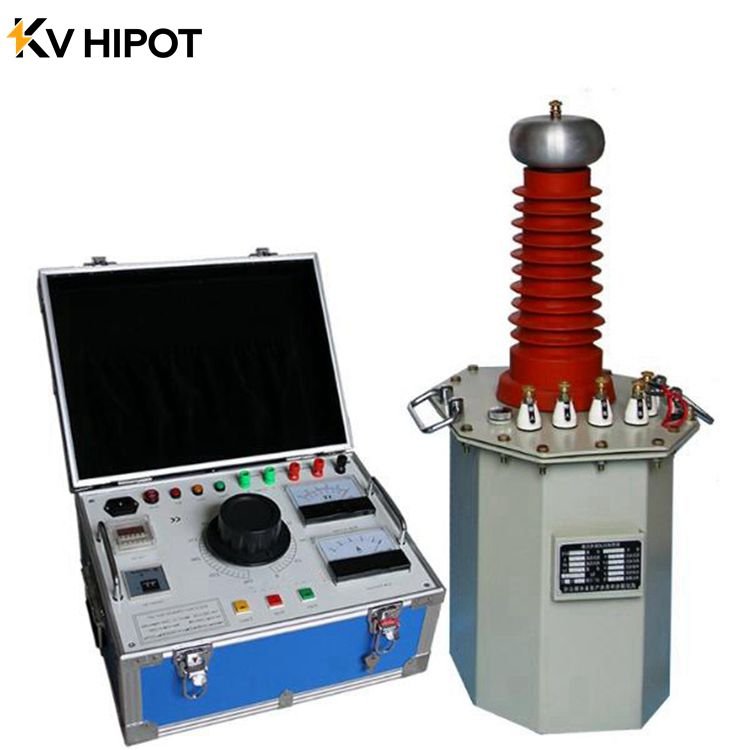
The equipment used in AC withstand voltage tests usually includes a test transformer, voltage-regulating equipment, voltage measuring devices, protective resistors, and overcurrent protection devices. The main types of equipment are described below.
How to Select a Test Transformer
The selection of a test transformer should first meet the test conditions of the equipment under test, and at the same time should be as economical and reasonable as possible. The main selection parameters of a test transformer are rated voltage, rated current, and rated capacity.
Rated voltage: The rated output voltage on the high-voltage side of the test transformer should meet the test voltage requirement of the test object, and the rated input voltage on the low-voltage side should match the output voltage of the voltage regulator.
Rated current: The rated current of the test transformer should meet the test current of the test object with some margin. Because the test object is mostly capacitive, the test current can be estimated using the following formula:
Ic = ω × Cx × Us
Where: Ic — Capacitive current of the test object during the test (mA); ω — Angular frequency of the power supply; Cx — Equivalent capacitance of the test object (μF); Us — Test voltage (kV).
Rated capacity: The rated capacity should not be less than P = Us × Ic.
Note: In any case, the test current must be less than the rated current of the test transformer.
Voltage waveform distortion rate: It is generally stipulated that the waveform distortion rate of a test transformer shall not exceed 5%.
Voltage-Regulating Equipment Requirements and Types
The test voltage in an AC withstand voltage test rises gradually from zero to the specified test voltage value. To ensure the reliability of the test, the voltage-regulating equipment should meet the following requirements:
- Smooth adjustment from zero to full voltage.
- The output voltage waveform should be as close to a sine wave as possible.
- The rated output voltage and rated capacity of the voltage regulator should match the test transformer.
Voltage-regulating equipment mainly includes autotransformer voltage regulators, moving-coil voltage regulators, induction voltage regulators, and motor-generator sets.
Autotransformer voltage regulators are the most widely used and structurally simplest voltage-regulating equipment. They have the advantages of smooth voltage adjustment, small leakage reactance, small losses, and small waveform distortion. However, because voltage regulation is performed by a sliding contact, their capacity is somewhat limited. Generally, their rated capacity and rated voltage are below 20 kVA and 500 V.
Moving-coil voltage regulators can have capacities from tens of kVA to hundreds of kVA, and voltages up to 10 kV. They can be used with large-capacity, high-voltage test transformers. To improve the test voltage waveform, a filter should be installed on the low-voltage side of the test transformer, consisting of an L-C series branch connected in parallel across the low-voltage side of the test transformer to filter out high-order harmonics in the test voltage. The C value is generally 6–10 μF.
Methods for Measuring Power-Frequency High Voltage
Measurement on the low-voltage side of the test transformer: For general porcelain insulation, circuit breakers, insulating tools, etc., the voltage on the low-voltage side of the test transformer can be measured and then converted to the high-voltage side voltage according to the turns ratio. This is only applicable when the load capacity is much smaller than the source capacity and the measurement accuracy requirement is not high.
Measurement with a voltage transformer: The primary side of the voltage transformer is connected in parallel across both ends of the test object, and the voltage is measured on the secondary side. The high-voltage side voltage is calculated from the measured voltage and the turns ratio of the voltage transformer. The voltage transformer should generally be not lower than Class 0.5, and the voltmeter not lower than Class 0.5.
Measurement with a high-voltage electrostatic voltmeter: The effective value of the power-frequency high voltage is measured directly with a high-voltage electrostatic voltmeter. The input impedance of the electrostatic voltmeter is extremely high, so it absorbs very little power from the measured circuit. Currently, domestic electrostatic voltmeters have ranges such as 30, 100, and 200 kV.
Measurement with a copper sphere gap: The sphere gap is a basic device for measuring power-frequency high voltage, with a measurement error within ±3%. The sphere gap measures the peak value of the AC voltage. The sphere gap distance S and the sphere diameter D should satisfy 0.05D ≤ S ≤ 0.5D to ensure accuracy.
Measurement with a capacitive voltage divider: A capacitive voltage divider consists of a high-voltage arm capacitor C1 and a low-voltage arm capacitor C2 connected in series. The voltage U2 across C2 is measured with a low-voltage voltmeter or oscilloscope, and the high voltage U1 is calculated from the voltage division ratio. When C2 >> C1, the voltage division ratio Ku = (C1 + C2)/C1 ≈ C2/C1.
Protective Resistor Requirements
In AC withstand voltage tests, a protective resistor is connected at the high-voltage output terminal of the test transformer to prevent damage to the transformer insulation when the test object flashes over or breaks down. The protective resistor serves both as overcurrent protection and as overvoltage protection.
The protective resistance value is generally 0.1–0.5 Ω/V, and it should have sufficient heat capacity. Water resistors or wire-wound non-inductive resistors are generally used.
Low-Voltage Overcurrent Protection Settings
The operating current of the overcurrent relay should be correctly set, generally to 1.3–1.5 times the rated current of the test transformer.
High-Voltage Overvoltage Protection Settings
The measuring sphere gap is adjusted to the distance corresponding to 1.2 times the test voltage; at this time, the sphere gap serves as an overvoltage protection device.
Power-Frequency High-Voltage Test Circuit and Component Labels
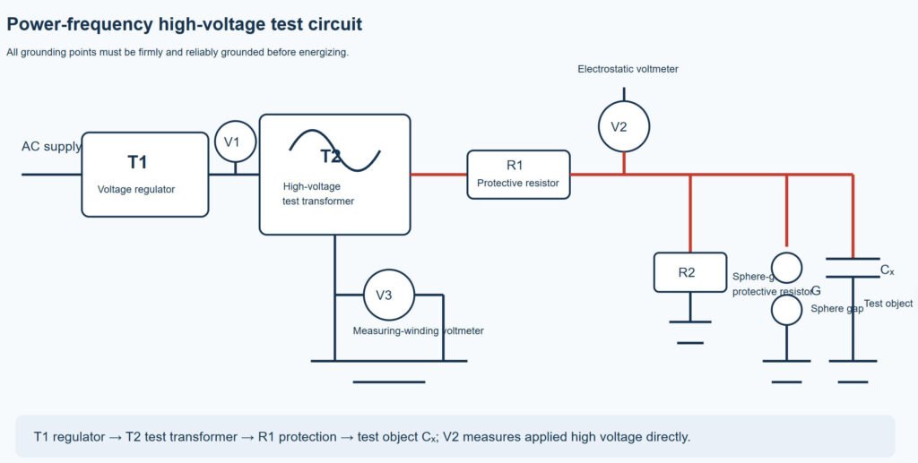
Figure 3-1-2. Power-frequency high-voltage test circuit diagram.
- T1 — Voltage regulator
- T2 — High-voltage test transformer
- V1 — AC voltmeter
- V2 — Electrostatic voltmeter
- V3 — AC voltmeter
- R1 — Transformer protective resistor
- R2 — Sphere-gap protective resistor
- Cx — Test object
- G — Sphere gap for overvoltage protection
How to Perform a Power-Frequency AC Withstand Voltage Test
- Confirm that the insulation resistance measurement, dielectric loss measurement, DC leakage current measurement, and dielectric loss measurement of the test object have all passed before performing the AC withstand voltage test.
- Make a preliminary estimate based on the test voltage and capacitance of the test object, and select a suitable test transformer and related equipment.
- When selecting a protective resistor for non-integral test equipment, consider matching the setting current of the overcurrent protection relay.
- Cut off the power supply to the test object, and remove or disconnect all related connections.
- Record the environmental conditions during the test: atmospheric pressure and temperature.
- Adjust the leveling screws at the bottom of the electrostatic voltmeter until its level indicates that the voltmeter is horizontal. Select the appropriate ranges of all relevant instruments.
- First perform a no-load test. Wire according to the test schematic diagram. The test equipment should be arranged reasonably, easy to operate, and comply with the relevant safety regulations. All grounding points in the test circuit should be firmly and reliably grounded. Finally, the wiring should be checked by the instructor. After confirming the wiring is correct, all personnel should leave the test area.
- After confirming that no one is in the test area, seal off the test area.
- Confirm that the voltage-regulator knob is at the zero position. It is strictly forbidden to apply voltage to the test object by impact closing.
- Turn on the power of the power-frequency high-voltage test transformer control console, close the switch, and raise the voltage uniformly. The voltage rise speed is not limited below 70% of the test voltage; thereafter, the voltage should be raised uniformly at a speed of about 3% of the test voltage per second.
- Apply 20%, 40%, 60%, and 80% of the test voltage, and record the readings of the low-voltage side voltmeter of the test transformer, the measuring-winding voltmeter, the electrostatic voltmeter, and the low-voltage side voltmeter of the divider. Take the output voltage of the voltage regulator as the abscissa and the voltages measured by the measuring winding, electrostatic voltmeter, and divider as the ordinates, and plot the no-load characteristic curves respectively.
- Connect two test objects with different capacitances into the test circuit in turn, and repeat steps 8–11. Plot two different load characteristic curves.
- Consult the sphere gap breakdown voltage table in the appendix, and adjust the measuring sphere gap to the distance corresponding to 1.2 times the test voltage; at this time, the sphere gap serves as an overvoltage protection device.
- Remove the electrostatic voltmeter from the test circuit. Find the power-frequency withstand voltage test voltage of the test object from the load characteristic curve. For the AC withstand voltage test of coupling capacitors and capacitive voltage dividers of capacitive voltage transformers, Code for Handover Test of Electric Equipment GB 50150-2016 stipulates that it should be carried out when necessary, and the test voltage should be 75% of the factory test voltage.
- After the experiment, cut off the power supply and hang the grounding rod on the high-voltage terminal of the test transformer.
- Measure the insulation resistance of the test object after the withstand voltage test. (The insulation resistance before and after the test should not show a significant decrease.)
Power-Frequency High-Voltage Test Report Requirements
- Write out the relevant calculations for equipment selection.
- Record the model and technical parameters of the equipment used.
- Prepare a test record table.
- Based on the recorded data, plot the calibration curves U=f(V1) of the power-frequency test transformer under no-load and loaded conditions. Plot the calibration curves measured by the measuring winding, electrostatic voltmeter, and divider with a low-voltage electrostatic voltmeter (or oscilloscope) on the same coordinate paper, and compare and analyze the differences among the several measurement methods.
- Provide the AC withstand voltage test voltage standard for shunt capacitors for reference.
- Based on the power-frequency withstand voltage test conditions, give a result analysis.
- For equipment with good insulation, there should be no breakdown, discharge, or other abnormal phenomena during the AC withstand voltage test.
During the test, if any of the following occurs, the cause should be further investigated:
- The current meter reading suddenly rises or the voltage meter reading suddenly drops during the test. At this time, the voltage should be reduced immediately and the power cut off.
- The overcurrent protection trips.
- The test object produces breakdown sound (or intermittent discharge sound), smoke, gas emission, burning smell, flashover, or combustion. At this time, the voltage should be reduced immediately and the power cut off.
- For organic insulating materials, general or local heating occurs after withstand voltage.
- The insulation resistance after withstand voltage decreases by about 30% compared with that before the test.
Safety Precautions for Power-Frequency High-Voltage Testing
- When the test object has large capacitance, there are two ways to measure high voltage: one is to measure directly at the high-voltage end of the test object to avoid damage to the insulation caused by the high voltage generated by the capacitive rise effect; the other is to find the test voltage from the calibration curve when the test object is loaded.
- The high-voltage connection line should be as short as possible, and the specified safe distance should be maintained from the grounding line or other grounded objects.
- After wiring is completed, all personnel should leave the high-voltage test area. The high-voltage test area and the operation area should be clearly separated by signs.
- The voltage rise should start from zero, and the voltage rise speed must meet the specified requirements.
- During operation, pay attention to the situation in the test area. In case of abnormal conditions, reduce the voltage and cut off the power at any time; in case of emergency, disconnect the power immediately.
- After the high-voltage test, the power supply must be cut off before entering the test area. After entering the test area, the grounding rod should first be hung on the high-voltage terminal of the test transformer to avoid accidents caused by misoperation such as forgetting to cut off the power.
- When the test object is an organic insulating material, it should be touched immediately after the test. If general or local heating occurs, the insulation is considered defective and should be dealt with in time before retesting.
- The insulation resistance of the test object should be measured after the withstand voltage test

 English
  ไทย
ไทย  Tiếng Việt
  العربية
  Русский
  Italiano
  Español
  한국어
한국어  Português do Brasil
  Français
  Español de México
  Português
  Türkçe
  Čeština
  Español de Argentina
  Slovenčina
  Dansk
Dansk  Polski
  Deutsch
  Ελληνικά
  O‘zbekcha
  Bahasa Indonesia
  Română