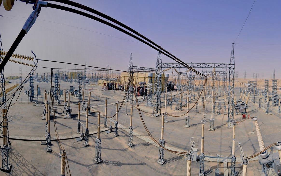
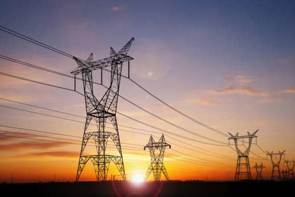
In today’s technologically driven world where reliable electrical infrastructure is paramount. As the power transmission cable is extensively used, Cables serve as the lifelines for power distribution, telecommunications, and various industrial applications, making their integrity and performance critical to ensuring safety, efficiency, and uninterrupted service. Cable testing plays a vital role in verifying that cables meet stringent standards and specifications before they are put into service, thereby preventing potential failures that could lead to costly downtime, safety hazards, and extensive repairs.
This article will talk about the methods of cable testing .The cable testing focused on insulation layer and the leakage , withstand voltage , dielectric loss and partial discharge characteristics of cable insulation .
Cable Insulation Resistance (IR) Measurement
Insulation resistance testing is used to check the soundness of cable insulation . Insulation resistance tester ( Megohmmeter insulation testers)has various of voltage levels including 500kV, 1000kV, 2500kV, 5000kV and 10kV. M meter is used to measure the resistance of insulation, which reflects the leakage characteristic of cable insulation.
As per the international standard IEC 62067, the insulation testing is performed between each conductor and the metallic screen/sheath, as well as between all conductors connected together. The test voltage shall be 4 kV DC for cables rated up to 18/30 (36) kV with a minimum duration of 1 minute. For cables rated above 18/30 (36) kV, the test voltage shall be 10 kV DC for a min duration of 1minute. The insulation resistance value measured after 1 minute shall not be less than 5 GΩ-km.
DC Dielectric test
DC dielectric test(dc hipot testing) is a common method to evaluate the leakage and dielectric characteristics of cable insulation. DC dielectric testing is to measure the leakage current through the insulation when a DC voltage is applied. Low leakage current indicates good insulation quality.
But DC dielectric test is not good method to test the power cable . DC dielectric test does not fully represent the actual withstand capability of cable. The sphere gap discharges, back-EMF effects, and fault masking can all lead to inaccurate or even damaging results when using DC testing.
- There is the limitations of DC dielectric testing for solid dielectric cables like XLPE. Solid dielectric cables like XLPE have small sphere gaps within the insulation layer.These sphere gaps can discharge at DC voltages, which enhances the apparent dielectric strength. This doesn’t accurately reflect the actual dielectric withstand capability of the cable.
- When the polarity of the applied DC voltage is reversed, a back-EMF effect occurs. This back-EMF can significantly reduce the dielectric strength of the cable, which is not captured by DC testing.
- When an XLPE cable has a fault, the DC test can sometimes “burn through” the fault.This can lead to a misleadingly high insulation resistance reading, hiding the underlying faults
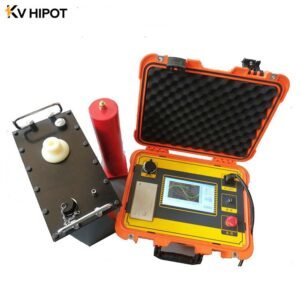
Very Low Frequency Testing (VLF Testing)
VLF testing is a AC withstand voltage testing mainly used on low voltage and middle voltage cable by the frequency range of 0.1 Hz to 0.01 Hz by outputting sine waveform . It is to identify the potential failure in the insulation lay of cable by the instantaneous voltage.
Advantages of VLF Testing for Cable Insulation
1)Reduced Voltage Stress
Lower Voltage Levels: VLF (Very Low Frequency) testing operates at significantly lower voltages compared to traditional hipot (high potential) testing.
he reduced voltage levels decrease the likelihood of damaging or accelerating the aging of cable insulation, which is crucial for older or deteriorating cables that might be more vulnerable to high-voltage stresses.
High-voltage dielectric testing can exacerbate existing issues in aging cables, while VLF testing provides a gentler alternative that helps maintain the integrity of such infrastructure.
2)Improved Sensitivity to Defects
Detection of Subtle Issues: VLF testing, with its lower frequency range (typically 0.1 Hz to 1 Hz), is more effective in detecting partial discharges and other subtle insulation defects.
3) Realistic Simulation of Operating Conditions
Mimicking Field Conditions: The sinusoidal waveform and lower frequency of VLF testing closely mimic the actual operating conditions that cables experience in the field.
Better Performance Evaluation: This realistic simulation helps in evaluating the cable’s performance under practical stresses, unlike the sudden voltage spikes seen in hipot testing.
Long-Term Reliability Insight: The results from VLF tests can provide a more accurate indication of the cable’s long-term reliability and expected service life.
4) Compact and Lightweight Test Equipment
VLF test equipment is generally more compact, lightweight, and easier to transport compared to power frequency withstand testing .This portability makes VLF testing more practical and accessible for field testing of installed cables, particularly in remote or difficult-to-access locations.
VLF testing offers numerous benefits over traditional AC withstand voltage testing, making it a preferred method for evaluating cable insulation, especially in scenarios involving older or deteriorating cables. Its ability to detect subtle defects, simulate real-world conditions, and provide a safer, more portable testing solution aligns with industry standards and helps ensure the reliability and longevity of electrical cable systems.

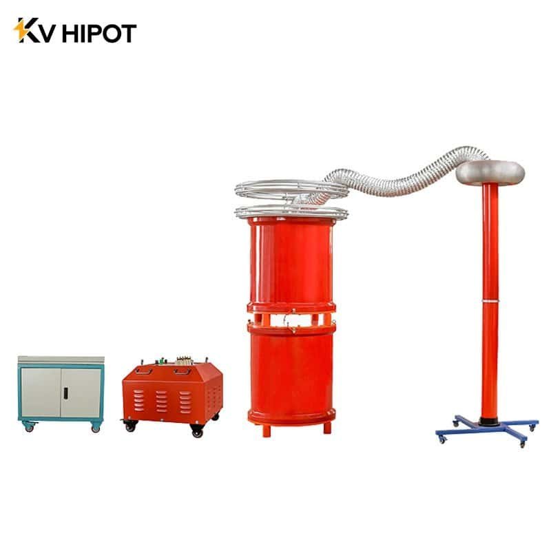
AC Resonance Testing
AC resonance test system is an effective solution to address the limitations of direct power frequency testing for long cables,
Principle of Operation:The AC resonance test system utilizes the inherent capacitance of the cable under test and an adjustable inductance to create a series resonant circuit. The output frequency is 30-300Hz.
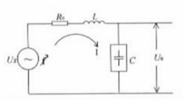
At the resonant frequency, the inductive and capacitive reactances cancel each other out, resulting in a very low impedance in the circuit.
The resonant circuit of AC resonance test system minimizes the reactive power requirements, leading to higher efficiency and lower energy consumption.
Flexible testing: The adjustable inductance allows the system to be tuned for cables of different lengths and capacitances.
Enhanced safety: The resonant circuit limits the test current, reducing the potential for damage to the cable under test.
However, during the application on site, Changes in cable capacitance due to temperature variations, aging, or other factors can shift the resonant frequency, requiring continuous adjustments to the inductor. Instability in the resonant condition can lead to inaccurate test results or even damage to the cable under test.Any issues or malfunctions in the various components can affect the overall performance and reliability of the test.

Dielectric Loss Measurement of cable
Cable insulation materials exhibit dielectric losses due to the inherent imperfections and polarization effects within the insulation.These losses, also known as dielectric dissipation or power factor(tanδ), are indicative of the quality and aging state of the insulation.
The dielectric loss (tan δ or DF) value provides insights into the condition of the cable insulation:Low dielectric loss indicates good-quality, well-maintained insulation.Increased dielectric loss may signify issues such as moisture ingress, thermal aging, or insulation degradation.
Aging and environmental factors: Factors like moisture, contaminants, and thermal stress can accelerate insulation degradation and increase dielectric losses. The measurement could not effectively detect partial degradation and dampness, including cable contact problem. It has limitations that make them less suitable for on-site testing.
PD Testing for cable testing
Partial Discharge is localized electrical discharges that occur within the insulation material, typically due to imperfections such as cracks, or moisture.
PD testing involves detecting and analyzing the small electrical discharges that occur within or on the surface of the cable insulation due to localized high-stress areas.
The presence of a sphere gap and moisture in the rubber-plastic cable insulation indicates potential weaknesses or defects in the insulation system.
Partial Discharge (PD) Behavior:At the rated DC voltage, there is only a short-time PD process or no PD at all. At the rated AC voltage, the partial discharge may or may not occur, and if it does, the process is short-lived.
The partial discharge measurement is typically performed only for specific cable parts, such as the middle contact and terminals.
Oscillating Wave Test
Oscillation wave test is a method used for testing the insulation of high-voltage power cables and other electrical equipment.
Based on the LCR damped oscillation principle, a damped oscillation loop is formed with the built-in high-voltage reactor, the high-voltage real-time solid-state switch and the cable. A power-frequency sinusoidal voltage wave is applied to the cable to collect and analyze the discharge signals at the potential defects of the cable.
It is used for the commissioning test of super high voltage cables.
In Conclude
- Even through there are some different measurement method for power cable. DC dielectric testing is easy to operate and it can find the phenomenon of breakdown. But DC leakage current is not effective at determining cable life. DC dielectric test does not fully represent the actual withstand capability of cable. Besides , it has been verified to be damaged solid dielectric insulation .
- VLF tester is compact and easy to use on site. VLF testing subjects the insulation system to a more realistic operating condition by applying a sinusoidal waveform at a frequency similar to that of the power system.According to international standard IEC 60060-3 and IEC 60060-3, VLF tester is a good choose for power cable diagnosis. But So far VLF test system is mainly used for ≤35kV HV/MV cables.
- AC Resonance Test system can effective detect the cable insulation . It is composed by variable frequency power supply , HV reactor , voltage divider and exciting transformer . It is generally used on 66kV or above . For a longer and higher voltage cable, AC Resonance test system is can be bulky, complex, and expensive to maintain.
- PD test can detect special parts of cable middle contacts and terminals. But It should has a high sensitive to the PD test system . Besides, Interference signals can significantly impact the detection and diagnosis of cable partial discharge during on-site tests. The three main sources of interference are: corona or partial discharge signals from nearby operating equipment, partial discharge signals from the AC withstand voltage test device itself, and corona signals generated by the leads of the AC withstand voltage test circuit.