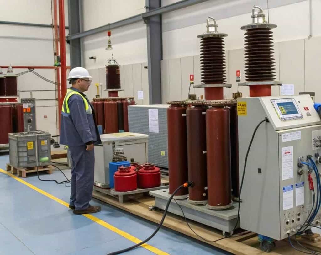
Transformers getting too hot is a serious concern. Overheating leads to insulation breakdown, unexpected failures, and costly downtime. The temperature rise test helps prevent this, ensuring your transformer operates safely. The temperature rise test measures how hot a transformer gets under full load conditions. It verifies that the transformer’s cooling system works correctly and that temperatures stay within safe design limits, preventing damage and ensuring reliable operation. Knowing the basics is good, but the details matter, especially for different types of transformers. As a manufacturer at KV Hipot, supplying reliable testing equipment globally, we understand these nuances. Let’s explore how this vital test applies in various situations and what the results really mean for equipment health.
What is the temperature rise test of a power transformer?
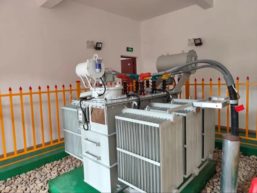
Power transformers handle huge amounts of energy. If their cooling fails, the consequences can be catastrophic, leading to major outages. This test specifically checks their ability to stay cool under pressure. For power transformers, the temperature rise test confirms the effectiveness of complex cooling systems (like oil, radiators, fans) under rated load. It ensures the transformer can reliably deliver power without dangerous overheating. !
Diving Deeper into Power Transformer Temperature Rise Testing
This test is arguably most critical for large power transformers because of the immense power they handle and the significant heat generated. Verifying the cooling design is non-negotiable. Test Methods: Simulating full load losses is key. Common methods include:
- Short-Circuit Method: Rated current is circulated in the windings (one shorted, one supplied) to simulate copper (load) losses. This heats the windings.
- Open-Circuit Method: Rated voltage is applied to one winding (usually LV) with the other open to simulate iron (no-load) losses. This heats the core. Often, these results are combined, or a back-to-back method (Sumpner’s test) is used for very large units. Temperature sensors measure top oil and average winding temperature (calculated via resistance change) until they stabilize. Why It’s Vital: IEC 60076-2 is a key standard here. The test confirms:
- The design (radiators, pumps, fans) can dissipate the generated heat.
- Insulation materials won’t degrade prematurely due to excessive heat.
- The transformer meets its specified temperature rise limits (e.g., 65°C average winding rise over ambient). Failure means the transformer cannot reliably handle its rated load.AspectDetailSignificanceObjectiveValidate cooling system for full load heatEnsures reliability, prevents thermal failurePrimary HeatCopper losses (windings), Iron losses (core)Dictates cooling requirementsKey MeasurementTop oil temperature, Average winding temperatureCompared against design/standard limitsStandarde.g., IEC 60076-2Provides standardized procedure and limits
How does the temperature rise test apply to current transformers?
Even smaller instrument transformers like CTs can overheat. This affects their accuracy and can pose a fire risk inside switchgear cabinets. Testing ensures they operate safely within their limits. Current transformers (CTs) also undergo temperature rise tests. This verifies they can handle their rated primary current and burden continuously without overheating, ensuring measurement accuracy and preventing damage.

Diving Deeper into Current Transformer Temperature Rise
While the power levels are much lower than power transformers, heat generation in CTs is still a concern. They are often enclosed in panels with other equipment, making heat dissipation important. Heat Sources: The main heat source is I²R loss in the primary and secondary windings due to the load current and the current flowing through the connected burden (meters, relays). Core losses are generally minimal but still contribute. Test Procedure: Rated primary current is passed through the CT, with the maximum specified burden connected to the secondary terminals. Temperatures are monitored (often on the casing or terminals, sometimes windings if possible) until they stabilize. The temperature rise must remain within the limits specified by standards (like IEC 61869-2) for the CT’s insulation class. Importance:
- Accuracy: Excessive temperature can change the resistance of the windings and potentially affect the magnetic properties of the core, leading to inaccurate current measurements.
- Safety: Overheating can damage the CT’s insulation and pose a fire hazard within enclosed switchgear or control panels.
- Longevity: Like any electrical device, running too hot shortens the lifespan of the CT. This test ensures the CT performs reliably and safely throughout its service life.
Is the temperature rise test different for dry type transformers?
Dry type transformers don’t have oil for cooling. This means heat must be removed differently, posing unique challenges. Testing must confirm their air-cooling method is sufficient. Yes, while the principle is the same (checking heat under load), the test for dry type transformers focuses on air circulation effectiveness and adherence to specific insulation class temperature limits, as there’s no oil.

Diving Deeper into Dry Type Temperature Rise Testing
Dry type transformers rely entirely on air to cool down, either through natural convection (AN – Air Natural) or forced air (AF – Air Forced) using fans. The temperature rise test validates this cooling method. Key Differences:
- No Oil Measurement: Obviously, there’s no top oil temperature to measure. Focus is primarily on winding temperatures.
- Insulation Class is Critical: Dry types use solid insulation systems rated for higher temperatures (e.g., Class F – 155°C, Class H – 180°C total temperature). The test verifies the winding hot spot temperature doesn’t exceed these limits under load (considering ambient + rise + hot spot allowance).
- Hot Spot Measurement: Measuring the actual hottest spot in the windings is more crucial and challenging. Methods include thermocouples embedded during manufacturing or calculations based on average winding resistance measurements.
- Enclosure Impact: If the transformer is enclosed, the test must account for the enclosure’s impact on airflow and heat dissipation. Test Method: Similar loss simulation techniques (short circuit, open circuit) are used. Sensors monitor winding temperatures and sometimes core/ambient air temperature within the enclosure. For AF units, fan operation is verified. The goal is to ensure the hottest spot temperature stays below the insulation system’s limit for the specified temperature rise (e.g., 80°C, 115°C, or 150°C rise).
What does “temperature rise” actually mean for a transformer?
Seeing “65°C rise” on a nameplate can be confusing. Does it mean the transformer runs at 65°C? Understanding this term is key to interpreting test results and ratings correctly. Temperature rise is the difference between the measured temperature of a specific part (like windings or oil) under load and the surrounding ambient air temperature. It’s not the final operating temperature.

Diving Deeper into Temperature Rise Meaning
Let’s break down this fundamental concept. “Temperature rise” specifies how much hotter than the surrounding air the transformer component is allowed to get when operating at its rated load. Calculation: Final Temperature ≈ Ambient Temperature + Temperature Rise Example: A transformer has an average winding temperature rise rating of 65°C. If the surrounding ambient air temperature is 30°C, the average temperature of the windings at full load will be approximately: 30°C (Ambient) + 65°C (Rise) = 95°C (Average Winding Temperature) Common Ratings:
- Oil-filled: Often see 65°C average winding rise over a 30°C average ambient. Top oil rise might be rated at 65°C as well. Older standards used 55°C rise.
- Dry Type: Higher rises are common due to higher temperature insulation systems, like 115°C or 150°C average winding rise over a 30°C ambient. Standards define the reference ambient temperature (e.g., 30°C average daily, 40°C maximum in IEC/IEEE). The temperature rise test verifies the transformer stays within its rated rise limit under these standard conditions. It’s a measure of the transformer’s ability to dissipate its own heat.
What does a typical temperature rise test setup involve?
Running a temperature rise test seems complicated. Knowing the basic components and arrangement helps understand how the test accurately measures the transformer’s thermal performance under load conditions. A temperature rise test setup includes the transformer, adjustable power sources to simulate load losses, temperature sensors placed strategically, and instruments to accurately measure and record temperatures and electrical parameters.
Diving Deeper into the Test Setup
Performing a reliable temperature rise test requires careful setup and instrumentation. Here are the essential parts:
- Transformer Under Test (TUT): The transformer itself, placed in an environment with stable, measured ambient temperature, free from drafts unless simulating specific site conditions.
- Loss Simulation Sources:
- For Winding (Load) Losses: A high-current, low-voltage AC source connected for the short-circuit test configuration. This simulates the heat from current flowing through the winding resistance (I²R losses). We at KV Hipot supply Primary Current Injection test sets often used for this.
- For Core (No-Load) Losses: A variable AC voltage source connected for the open-circuit test configuration. This simulates heat from magnetizing the core (hysteresis and eddy current losses).
- Temperature Sensors:
- Thermocouples or RTDs: Placed to measure ambient air temperature, top oil temperature (for liquid-filled units), and potentially surface temperatures.
- Winding Resistance Measurement: Used to calculate the average winding temperature based on the change in resistance from a known cold state. Precision resistance measurement equipment is needed.
- (Optional) Fiber Optic Sensors: Can be embedded directly in windings for hot-spot measurement.
- Measurement & Recording: Voltmeters, ammeters, wattmeters to monitor the electrical inputs, and data loggers or monitoring systems to record temperatures over time until stabilization is reached (typically when the rate of change is less than 1°C per hour). Safety precautions are paramount due to the voltages and currents involved.
How hot is too hot for a transformer?
It’s natural to worry if a transformer feels very warm. Knowing the actual temperature limits helps distinguish normal operating heat from a potentially damaging overheating situation requiring attention. “Too hot” depends on the transformer’s design and insulation system. It’s determined by adding the maximum ambient temperature, the rated temperature rise, and a hot-spot allowance, which must not exceed the insulation’s thermal limit.
Diving Deeper into Maximum Safe Temperatures
There isn’t one single temperature that’s “too hot” for all transformers. The limit is specific to the unit’s design, primarily its insulation system. Here’s how the maximum operating temperature is generally determined: Key Factors:
- Maximum Ambient Temperature: Standards usually assume a maximum ambient air temperature, often 40°C (e.g., per IEEE/IEC standards). Site conditions might differ.
- Rated Temperature Rise: This is the value specified on the nameplate (e.g., 65°C average winding rise). It’s the maximum allowable temperature increase above ambient at full load.
- Hot Spot Allowance: The actual hottest spot inside the winding is always hotter than the average winding temperature measured by resistance. Standards provide an allowance for this difference (e.g., 10°C or 15°C for oil-filled, potentially higher for dry-types). Calculation Example (Oil-filled, 65°C rise): Max Hot Spot Temp = Max Ambient + Avg. Winding Rise + Hot Spot Allowance Max Hot Spot Temp ≈ 40°C + 65°C + 15°C = 120°C Insulation System Limit: This calculated maximum hot spot temperature must be below the thermal limit of the transformer’s insulation system (e.g., typically 105°C or 110°C limit for older mineral oil/paper systems, higher for newer systems or dry types like 155°C for Class F, 180°C for Class H). Exceeding the insulation’s thermal limit drastically shortens the transformer’s life due to accelerated aging.
What is the temperature rise rating on a transformer nameplate?
Transformer nameplates contain lots of information. Understanding the temperature rise rating is crucial for proper application and ensuring the transformer isn’t overloaded thermally in its operating environment. The temperature rise rating on the nameplate specifies the maximum allowed temperature increase of the windings (average) and possibly the insulating fluid (top level) above the ambient temperature when operating at full load.
Diving Deeper into Nameplate Temperature Rise Ratings
This rating is a key piece of design information verified by the temperature rise test. It tells you how much heat the transformer is designed to handle and dissipate. Common Ratings Explained:
- 65°C (or 65K): Often refers to the maximum average winding temperature rise over the ambient temperature (usually assumed as 30°C average / 40°C max). This is common for modern liquid-filled distribution and power transformers.
- 55°C: An older standard, indicating a lower allowable average winding temperature rise. These transformers generally run cooler or have lower power density.
- 55/65°C: This indicates a dual rating. The transformer can operate continuously with a 55°C average winding rise at its base kVA rating. It can also handle a higher load (typically 112% of base kVA) which results in a 65°C average winding rise.
- Oil Rise: Sometimes a separate rise is given for the top oil temperature (e.g., 65°C or 55°C).
- Dry Type Ratings: These use insulation class letters (like F or H) and associated temperature rise values (e.g., 115°C or 150°C average winding rise). Understanding this rating is vital for engineers like Muhammad or factory owners like Spencer. It ensures they select a transformer suitable for the expected load and the site’s ambient temperature conditions, preventing premature failure due to overheating. It links directly back to the factory tests we perform and the equipment KV Hipot provides.
Conclusion
The temperature rise test is crucial for transformer health. It verifies cooling performance, ensuring safe operation within limits, preventing failures, and maximizing the transformer’s lifespan and reliability.


