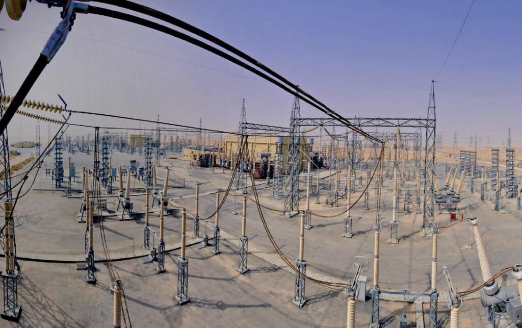
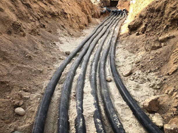
In the unforgiving desert, a power outage can grind all operations to a complete halt.
Saudi Arabia’s power infrastructure relies heavily on a medium-voltage grid anchored by 13.8 kV and 33 kV circuits. These voltage levels strike the ideal balance between power capacity and transmission efficiency, connecting substations, industrial parks, and entire urban areas. A stable supply is critical for supporting refineries, data centers, and large-scale infrastructure.
Unlike many other regions, Saudi Arabia faces unique environmental challenges: ambient temperatures soaring to 50°C, persistent sand intrusion, and high coastal humidity. Under these extreme conditions, insulation stress is significantly magnified. Consequently, the Saudi Electricity Company (SEC) implements rigorous testing protocols to ensure that every installed cross-linked polyethylene (XLPE) or ethylene-propylene rubber (EPR) cable can withstand expected operational loads.
Typically, 13.8 kV feeders supply urban loads and smaller industrial users, while 33 kV circuits handle primary distribution to main substations and major industrial facilities. Before energization, each cable section must undergo testing to verify the integrity of its joints and terminations. The SEC’s 2023 Reliability Report indicates that nearly 70% of medium-voltage feeder failures are traceable to installation defects. This statistic underscores exactly why standardized Very Low Frequency (VLF) testing is mandatory for every new or rehabilitated circuit.
Ultimately, power reliability and system safety depend on rigorously testing these cables before they are energized.
| Voltage Level | Application Area | Cable Type | Typical Circuit Role | Common Test Type |
| 13.8 kV | Urban feeders, distribution substations | XLPE | Outgoing feeder circuits | VLF 0.1Hz sinusoidal test |
| 33 kV | Sub-transmission, large consumer supply | XLPE | Infeed from main substation | VLF withstand test |
Medium-Voltage Cable Test Standards:
Comparing SEC Requirements to IEC 60502-2 (2024) and IEEE 400.2
EPC contractors often struggle to reconcile local Saudi Electricity Company (SEC) requirements with international standards, leading to uncertainty when selecting test voltage levels. In reality, SEC’s insulation withstand testing aligns closely with the Very Low Frequency (VLF) guidelines outlined in IEEE 400.2:2023 and IEC 60502-2:2024. Both international documents define the required test voltage as 3U₀ RMS (where U₀ is the phase-to-ground voltage of the cable system). Furthermore, due to the risk of space charge accumulation, the IEC explicitly advises against DC testing for cross-linked polyethylene (XLPE) cables, instead recommending the VLF sinusoidal method.
| Source Standard | Recommended Voltage | Basis (U₀) | Test Duration | Frequency Type |
| IEC 60502-2 (2024) | 3 × U₀ | Phase-to-ground voltage | 15-60 min | 0.1 Hz Sine |
| IEEE 400.2 | 3 × U₀ | Phase-to-ground voltage | 15-60 min | 0.1 Hz Sine |
| SEC Guide (2022) | Same as IEC | 8 kV (13.8 kV) / 19 kV (33 kV) | 30 min typical | 0.1 Hz Sine |
Since most Saudi projects reference SEC procedures—which mirror IEEE and IEC standards—a critical practical step for engineers is verifying the output display of their test equipment. It is vital to confirm whether the tester indicates root-mean-square (RMS) voltage or peak voltage to ensure the correct stress is applied.
SEC directly bases its requirements on IEEE 400.2 and the 2024 update of IEC 60502-2. Both standards converge on the same core methodology: conducting 0.1 Hz VLF testing on new and repaired cables using a sinusoidal wave with an RMS voltage of 3U₀. IEEE 400.2 (2023) categorizes tests into installation, acceptance, and maintenance.
For the installation and acceptance of XLPE cables, it specifies a 3U₀ RMS voltage applied for a duration ranging from 15 to 60 minutes. IEC 60502-2 (2024) reinforces this voltage level and reiterates the caution against DC testing, noting that trapped space charge can significantly shorten insulation life.
SEC has codified these guidelines in its document 33-TMSS-09, which mandates a 30-minute, 3U₀ RMS withstand voltage test for all cable sections rated at 13.8 kV or 33 kV. This specific voltage level applies an insulation stress approximately 2.5 to 3 times the normal operating load. Testing below this threshold might yield a false “pass,” failing to detect latent dielectric defects or weaknesses related to aging.
The primary advantage of VLF sine wave testing is its ability to simulate the electric field stress of power-frequency AC while requiring significantly less power. Furthermore, if supported by the equipment, sinusoidal VLF allows operators to perform more accurate partial discharge (PD) measurements. This combination of effective high-stress insulation testing and low power demand has established VLF as the global standard for medium-voltage cable acceptance.
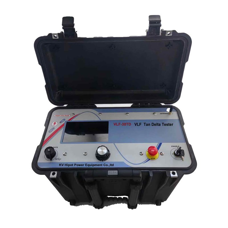
How to calculate the correct injection voltage for 13.8kV and 33kV cross-linked polyethylene cables, using a VLF Tester ?
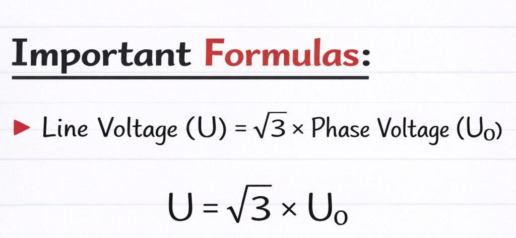
The formula is as below A fundamental prerequisite for accurate VLF testing is distinguishing between the system’s rated line-to-line voltage U,and the phase-to-ground voltage U₀.Standards such as IEEE 400.2 base their withstand test requirements on multiples of U₀.
Incorrect voltage injection is one of the most frequent mistakes in field testing, especially when the VLF machine displays peak values but engineers assume RMS.
To calculate the proper test voltage, the formula is simple:
RMS × 1.414 = Peak.
For a 13.8kV cable, U₀ is around 8kV, so 3U₀ = 24kV RMS (34kV Peak).
For a 33kV cable, U₀ is roughly 19kV, so 3U₀ = 57kV RMS (81kV Peak).
| Cable Rating | U0 (Phase–Ground) | Test Voltage (3U0 RMS) | Equivalent Peak Voltage | Duration | Waveform |
| 13.8kV | 8kV | 24kV RMS | 34kV Peak | 15–60 minutes | Sine 0.1Hz |
| 33kV | 19kV | 57kV RMS | 81kV Peak | 15–60 minutes | Sine 0.1Hz |
This clear separation between RMS and Peak ensures the injected voltage matches SEC acceptance criteria. Applying only 24kV Peak instead of RMS would under-test the insulation by as much as 30%, leaving defects undetected. Real field failures have confirmed this issue in multiple SEC sites, especially in desert conditions with XLPE aging.
Practical experience and on-site insights for the SEC project
1. Core Principles and Standards Basis
Saudi Electricity Company (SEC) network security policy mandates Very Low Frequency (VLF) testing for all medium voltage cables during commissioning and diagnostics. SEC acceptance requirements are generally framed based on the principles of international standards IEEE 400.2 and IEC 60502-2. Adhering to these standards ensures reliable cable operation under high load conditions and avoids costly project rework due to testing non-compliance.
The fundamental SEC test requirement is: Perform a voltage withstand test on the cable using a 0.1Hz sinusoidal wave VLF voltage.
2. Specific Test Parameter Indicators (Acceptance Criteria)
The core assessment indicator for the test is that the cable must withstand a voltage of 3U₀ RMS for a duration of 15 to 60 minutes.
The criterion for passing acceptance is: No insulation breakdown and no abnormal leakage current during the test.
The specific test values converted according to common SEC system voltages are as follows:
For 13.8kV System Cables:
Target Test Voltage (RMS): 24 kV RMS (Corresponding Peak Voltage: approx. 34 kV Peak)
For 33kV System Cables:
Target Test Voltage (RMS): 57 kV RMS (Corresponding Peak Voltage: approx. 81 kV Peak)
3. Critical Operation Warning: Confusion between RMS and Peak
This is the most common source of errors on-site and must be prioritized.
Standards and SEC requirements always refer to RMS (Root Mean Square) values. However, VLF test equipment usually displays both RMS and Peak values simultaneously. Misreading these values can lead to serious under-voltage testing and erroneous “pass” conclusions.
Mathematical Relationship (Sinusoidal Wave): Peak = RMS × √2 (approx. 1.414).
Critical Example (33kV Cable): To inject the required 57 kV RMS voltage into a 33kV cable, your test machine must be capable of outputting approximately 81 kV Peak voltage.
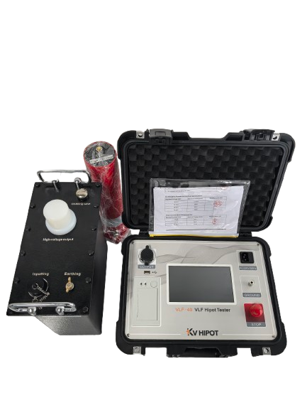
Equipment Trap: Many standard commercial “60kV VLF Testers” have an actual maximum output of only 60kV Peak (or slightly higher). This means they absolutely cannot meet the 3U₀ requirement (57kV RMS / 81kV Peak) for 33kV cables. Always confirm equipment rating capabilities before starting.
4. SEC Project Field Practices and Insights
Based on the supervision and analysis of numerous VLF tests on 13.8kV and 33kV networks in the region, here are key practical points for the field:
A. Machine Capacitance Limits and Frequency Adjustment:
The standard VLF frequency is 0.1 Hz. However, long cable runs common in SEC distribution networks have high capacitance (high µF values). If the cable is too long, the VLF machine may trip due to overcurrent at 0.1 Hz because it cannot provide sufficient charging current.
Countermeasure: You may need to lower the frequency to 0.05 Hz or 0.02 Hz to complete the test.
Note: While IEEE permits lower frequencies, SEC engineers usually prefer keeping it at 0.1 Hz whenever possible. If you must lower the frequency, ensure it is noted in the test report and obtain prior approval from the supervising engineer (SE).
B. Terminations are the Main Weak Point:
Experience shows that over 90% of VLF failures during commissioning occur at terminations (cable lugs/stress cones) or intermediate joints, rather than in the main cable insulation body. VLF is excellent at detecting workmanship errors (such as unclean cuts, residual semi-conductive layers, or air voids).
Countermeasure: Ensure terminations are extremely clean before testing and maintain sufficient safety clearance from ground to prevent external flashovers that are not actual cable body failures.
C. Use “Burn” Mode with Caution:
If a cable fails the VLF withstand test, do not switch immediately to “Burn” mode without permission. While burning reduces fault impedance to facilitate fault location (via thumping/surge discharge), it severely damages the insulation surrounding the fault point. This can potentially turn a simple joint repair job into a major project requiring the replacement of an entire section of cable.
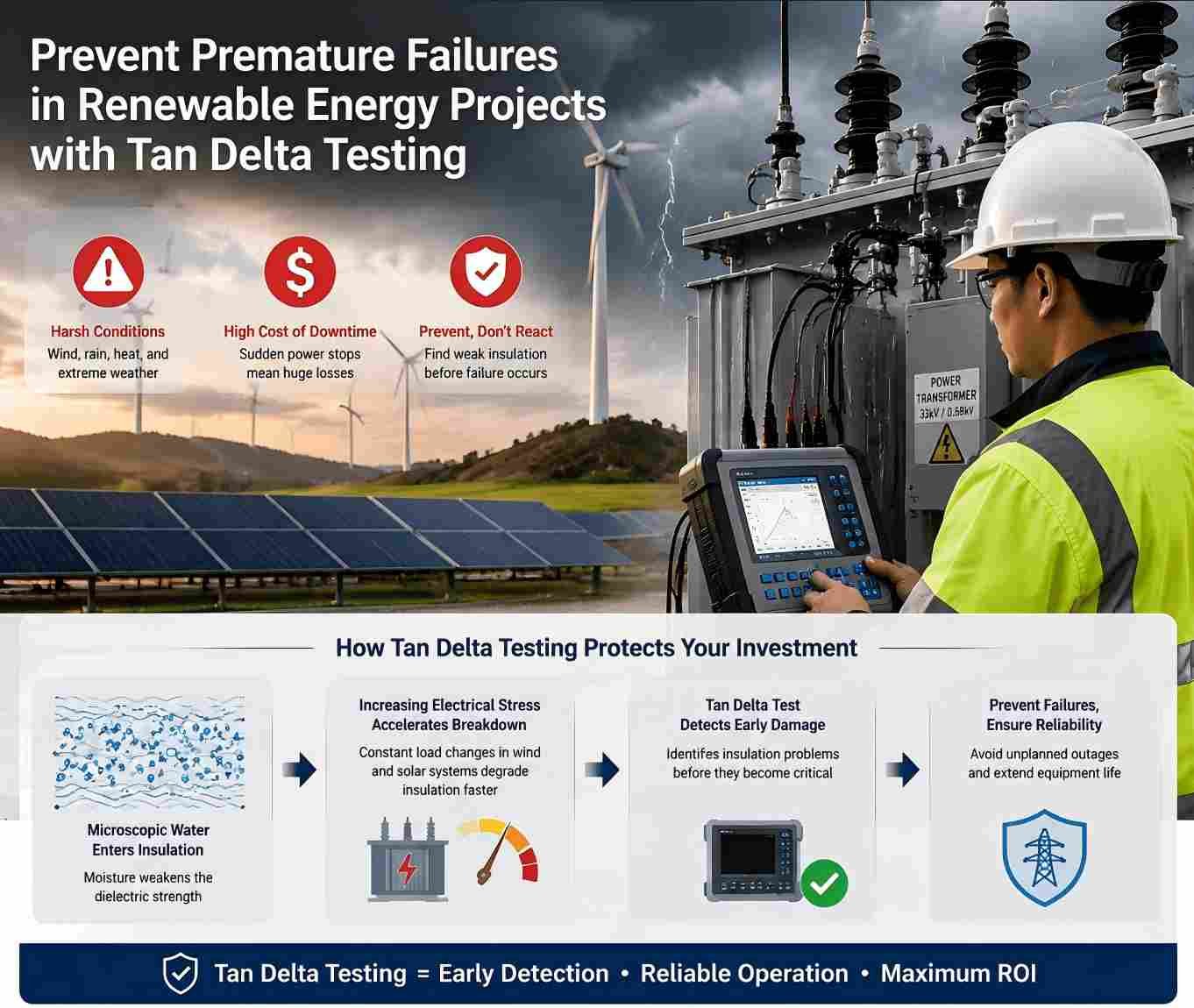
5. Advanced Diagnostic Trend: Dielectric Dissipation Factor (Tan Delta)
Although VLF withstand voltage testing is a “pass/fail” destructive test, SEC increasingly encourages (and sometimes mandates on critical circuits) performing a VLF Tan Delta (Dielectric Dissipation Factor) diagnostic test before conducting the high-voltage withstand test. This allows for a non-destructive assessment of the insulation’s health condition before subjecting the cable to high stress.