

Working with high-voltage equipment comes with serious risks. A hidden flaw in the insulation can lead to sudden, catastrophic failures, damaging expensive equipment and creating major safety hazards.
An HV test kit, or Hipot tester, is the professional solution for verifying electrical insulation integrity.
An HV (High Voltage) test kit is a piece of electrical equipment used to perform a high potential (Hipot) test. It applies a voltage much higher than the normal operating voltage to a component. This test checks for insulation breakdown and ensures the equipment can safely handle overvoltage conditions.
Now that you know what an HV test kit is, you can see its importance. But the real value comes from understanding what it means to conduct an HV test and how these kits are used in practice. We will explore what an HV test means, look at common testers like the 5kV model, and then walk through the procedures for testing critical assets like cables and transformers. This will give you the practical knowledge you need to ensure electrical safety and reliability.
What Does an HV Test Mean, and What Is a 5kV Tester Used For?
The term “HV test” can seem vague. You know it’s important, but you might not be sure what it involves or which tester is right for the job. Using the wrong tool can lead to inaccurate results or even damage the equipment you are trying to protect.
An HV test, or Hipot test, means applying a high voltage to a device to ensure its insulation is strong enough to prevent dangerous current leakage. A 5kV HV tester is a specific type of Hipot tester that generates up to 5,000 volts. This makes it perfect for testing low-voltage equipment like motors, generators, and industrial appliances.
The application always dictates the right tool. An HV test is a fundamental “go/no-go” safety check. It doesn’t measure the quality of the insulation; rather, it confirms that the insulation meets a minimum required strength. The test intentionally stresses the insulation to expose any hidden weaknesses, such as pinholes, cracks, or contamination, that could lead to failure under normal operating conditions.

A 5kV tester is a very common tool because its voltage range is ideal for production line testing of consumer electronics, verifying the windings in electric motors, or checking the insulation on switchgear and wiring used in standard 480V or 600V industrial systems.
Understanding Test Voltages
The required test voltage depends entirely on the equipment being tested. Here is a simple breakdown.
| Tester Type | Typical Applications | Why this Voltage? |
|---|---|---|
| 5kV Tester | Motors, generators, switchgear, appliances, wiring on low-voltage systems. | A common rule of thumb for Hipot testing is (2 x Operating Voltage) + 1000V. For 480V systems, this falls well within the 5kV range. |
| 30kV-50kV Tester | Medium voltage (MV) cables, distribution transformers, insulators. | These components operate at higher voltages (e.g., 15kV, 25kV), so they require a significantly higher test voltage to verify their insulation integrity according to standards like IEEE and IEC. |
| 100kV+ Tester | Transmission-class transformers, high-voltage bushings, research laboratories. | Used for equipment on high-voltage transmission grids, requiring very high test potentials to simulate lightning strikes or switching surges. |
What is the General Procedure for an HV Test?
Knowing you need to perform an HV test is one thing, but doing it safely and correctly is another. An improper procedure is dangerous and can give you useless data. Mistakes like poor grounding can lead to electric shock or damage to both the tester and the equipment.
A standard HV test procedure involves four key steps:
1) Isolate and de-energize the equipment completely.
2) Connect the test leads correctly (high voltage to the conductor, ground to the return path.
3) Apply the voltage gradually and hold for the specified time.
4) Safely discharge the equipment after the test.
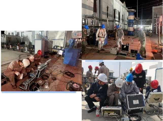
I always tell our clients, the most important part of the test happens before you even turn the tester on. Safety is the top priority. You must confirm that the equipment is fully de-energized, use the right personal protective equipment (PPE), and set up a safe test area with barriers and warning signs to keep untrained personnel away. This non-negotiable process ensures the safety of the operator, protects the equipment, and guarantees the integrity of your test results. Following a clear, step-by-step procedure removes guesswork and minimizes risk, allowing you to perform the test with confidence every single time.
Step-by-Step HV Test Procedure
This table outlines the essential steps for a safe and effective HV test.
| الخطوة | الإجراء | Critical Details & Safety Notes |
|---|---|---|
| 1. Preparation | Isolate the device under test (DUT) from the power system. Ensure it’s de-energized and locked out. | Verify with a voltmeter that there is zero energy. This is the most critical safety step. The area should be cordoned off with warning tape. |
| 2. Connection | Connect the HV test kit. The high voltage lead goes to the conductor, and the ground/return lead goes to the equipment’s ground. | Ensure connections are clean and secure to prevent arcing. For a multi-conductor cable, all other conductors should also be grounded. |
| 3. Test Execution | Set the required test voltage and maximum leakage current limit on the tester. Gradually ramp up the voltage to the target level. Hold for the specified duration (e.g., 60 seconds). | Monitor the leakage current meter. A steady, low current is good. A sudden jump indicates an impending breakdown. The test should automatically trip if the current limit is exceeded. |
| 4. Completion | After the test time, slowly ramp down the voltage to zero. Do not disconnect the leads yet. Use the tester’s discharge function or a separate discharge stick to ground the DUT. | The DUT can hold a dangerous capacitive charge. Always confirm it is fully discharged before touching any connections. This can take several minutes for long cables. |
How Do You Perform an HV Test on Cables?
Cables are the arteries of any power system. Their long lengths and installation environment make them vulnerable to hidden damage from moisture, sharp bends, or accidental digging. A single insulation failure in a critical cable can shut down an entire facility or neighborhood.
An HV test for cables involves applying a high voltage between the cable’s central conductor and its metallic shield or ground. This test checks the primary insulation for any weaknesses. For modern medium voltage (MV) cables, a Very Low Frequency (VLF) AC test is the industry standard because it’s effective without being as harsh as older DC tests.
Many of our clients in power distribution and renewable energy rely on our VLF Hipot testers. A contractor installing cables for a new wind farm, for instance, must perform a VLF withstand test on every single cable before commissioning the project. It is both a contractual requirement and an industry best practice. The main challenge with cable testing is their high capacitance, which makes testing with standard 50/60 Hz AC impractical in the field. This is why VLF (0.1 Hz) and DC methods were developed. However, for modern XLPE insulated cables, DC testing is no longer recommended by standards like IEEE 400.2 because it can be ineffective and potentially damaging.
HV Test Methods for Cables
| Test Method | Cable Type | Procedure Highlights | Pros & Cons |
|---|---|---|---|
| DC Hipot Test | Older, paper-insulated lead-covered (PILC) cables. | Apply a high DC voltage. The leakage current should be low and stable. | Pro: Simple, portable equipment. Con: Can be damaging to modern XLPE/EPR insulation and may not find all defect types. Not recommended for modern cables. |
| VLF AC Hipot Test | Modern solid-dielectric cables (XLPE, EPR). | Apply an AC voltage at 0.1 Hz. The test is a withstand test; the cable either passes or fails. This is the industry-preferred method (IEEE 400.2). | Pro: Very effective at finding serious defects like water trees without harming healthy insulation. Con: Equipment is more complex than DC testers. |
| 50/60 Hz AC Hipot Test | Short cable lengths, factory testing. | Apply normal frequency AC voltage from a powerful source. | Pro: Simulates real-world stress. Con: Requires very large, heavy, and expensive equipment to test long cables due to their high capacitance. Not practical for field use. |
How Is an HV Test Conducted on a Transformer?
A transformer is one of the most expensive and critical assets in any power system. Its internal insulation is complex and can degrade over time due to heat, moisture, and electrical stress. A transformer failure is a major event, often resulting in long outages and expensive replacements.
An HV test on a transformer, known as an applied potential test, involves applying a high AC voltage to one winding for one minute while all other windings and the tank are grounded. This test verifies the integrity of the insulation between the winding and the other grounded parts of the transformer.
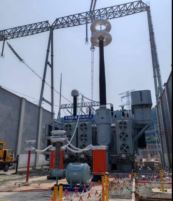
AC Hipot tester is always part of the package. A client who manufactures transformers uses one on every single unit before it leaves the factory. For them, it is the final quality check that proves the winding insulation meets international standards like IEEE C57. This test checks the primary insulation system—the barriers between the windings and between the windings and the grounded core and tank. However, it does not test the insulation between the individual turns of a winding. For that, a separate test called an “induced potential test” is required, which uses a higher frequency to induce a high voltage within the winding itself.
Key HV Tests for Transformers
| Test Name | Purpose | How It’s Done | What a “Pass” Looks Like |
|---|---|---|---|
| Applied Potential Test (Hipot) | To check the main insulation between windings, and between windings and ground (tank). | Apply a high AC voltage to one winding at a time, with all other windings and the tank grounded. Hold for 60 seconds. | The transformer withstands the voltage for the full duration without a sudden increase in current or breakdown. |
| Induced Potential Test | To check the turn-to-turn and inter-layer insulation within a single winding. | The primary winding is energized at a higher frequency (e.g., 400 Hz) to induce 2x the rated voltage in the secondary winding without saturating the core. | No breakdown or unusual noise during the test. This test is crucial as a normal Hipot test doesn’t stress turn-to-turn insulation. |
| Insulation Resistance (Megger) Test | To measure the overall quality of the insulation in megohms. | An HV DC voltage (e.g., 5kV) is applied and the resistance is measured after one minute. | A high resistance value (e.g., >1000 MΩ) indicates dry and clean insulation. This is often done before a Hipot test as a preliminary check. |

